Fuel System: 1G-25
Installation
Installation is in the reverse order of removal with special
attention to the following steps.
Do not re-use O-ring and cushion once
removed.
Always use new parts.
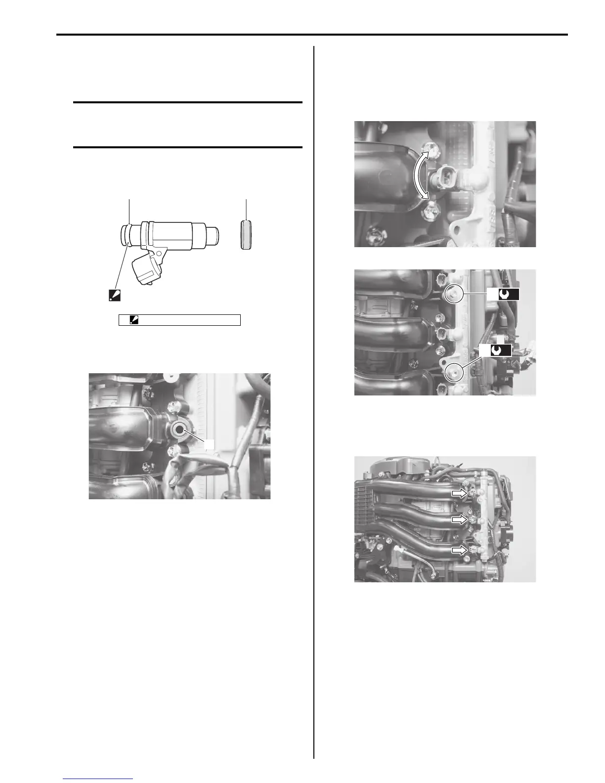
1) Replace the injector O-ring (1) with a new one using
care to avoid nicks or cuts during installation.
2) Replace the injector cushion (2) with a new one and
install to the intake manifold.
3) Apply a thin coat of fuel to injector O-rings, then
install the injectors into the delivery pipe and intake
manifold.
Make sure that the injectors rotate smoothly.
4) Tighten the delivery pipe bolts (3) and make sure
that the injectors rotate smoothly.
Tightening torque
Fuel delivery pipe bolt (a): 11 N·m (1.1 kgf-m, 8.0
lbf-ft)
5) Reconnect the fuel feed hose and fuel line securely.
6) Connect the lead wire connector to the injectors
securely.
7) Make sure the emergency stop switch lock plate is in
place.
Shift into “Neutral” position.
8) Squeeze the fuel primer bulb until you feel
resistance.
Turn ignition switch “ON” for 3 seconds (to operate
fuel pump), then turn it “OFF”.
Repeat this (“ON” and “OFF”) procedure 3 or 4 times
to pressurize the fuel system.
Check for fuel leaks around the fuel injectors.
“A”: Apply fuel to O-ring.
1 2
“A”
2
(a)
3
(a)
3



 To Next Page