Housing and Bracket: 2A-25
• Tighten clamp bracket shaft nut (10) to specified
torque.
• After tightening clamp bracket shaft nut to specified
torque, bend lock washer edge toward nut to secure
nut.
Tightening torque
Clamp bracket shaft nut (a): 43 N·m (4.3 kgf-m,
31.0 lbf-ft)
• Tighten two PTT lower shaft bolts, pre-coated with
thread lock, to specified torque.
Tightening torque
PTT lower shaft bolt (b): 50 N·m (5.0 kgf-m, 36.0
lbf-ft)
: Thread lock cement 99000–32050 (SUZUKI
Thread Lock 1342 (50 g))
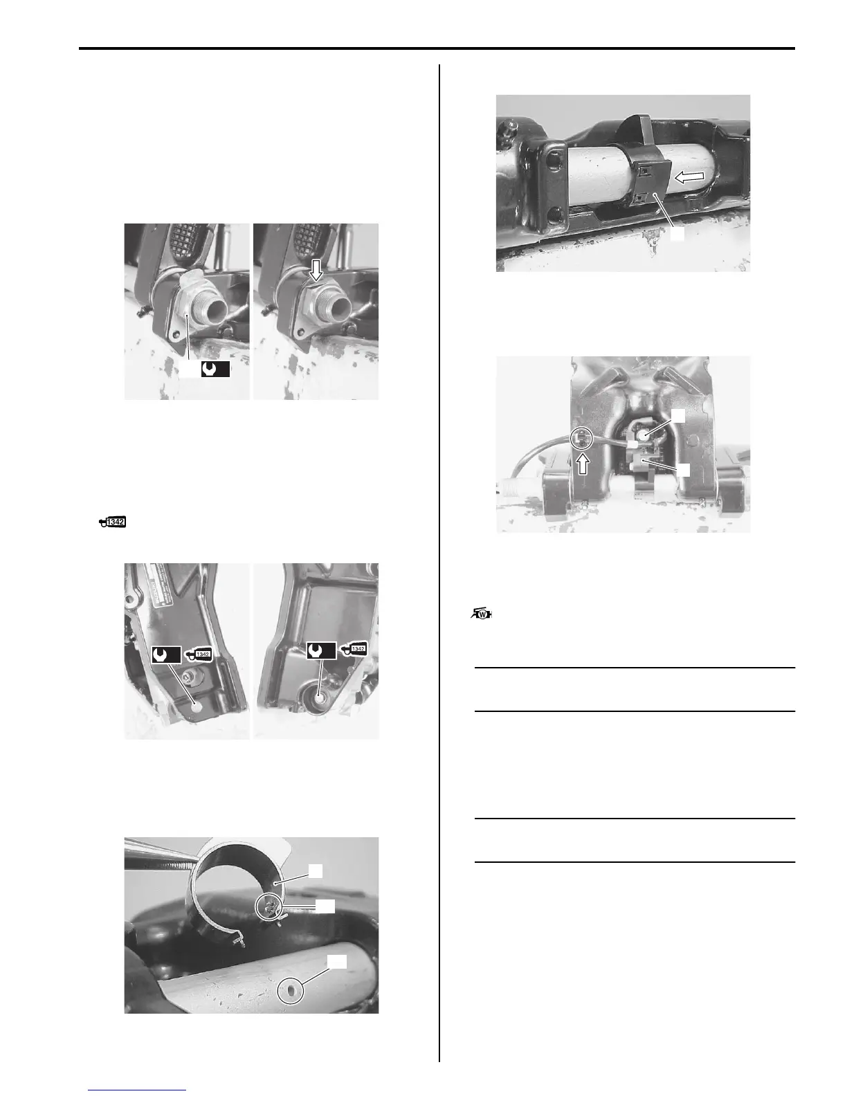
Trim Sensor and Trim Sensor Cam
• Install the upper trim sensor cam (1) engaging its
locating pin “A” with the clamp bracket shaft hole “B”.
• Install the lower trim sensor cam plate (2).
• Install the trim sensor assembly (3), then secure it
with bolts (4).
• Secure switch lead wire with cable tie.
Steering Bracket
• Apply water resistant grease to steering bracket shaft.
: Grease 99000–25161 (SUZUKI Water
Resistant Grease (250 g))
NOTE
Apply grease to bushings, oil seal lip and
pilot shaft portion of steering bracket.
• Install upper bushing (1) and washer (2) to swivel
bracket.
• Install lower bushing (3) and swivel bracket seal (4) to
swivel bracket.
NOTE
Install bracket seal (4) with oil seal lip (spring
side) facing downward.
(b)
(b)
1
“A”
“B”
2
3
4