0B-10 Maintenance and Tune-Up:
Shim size chart
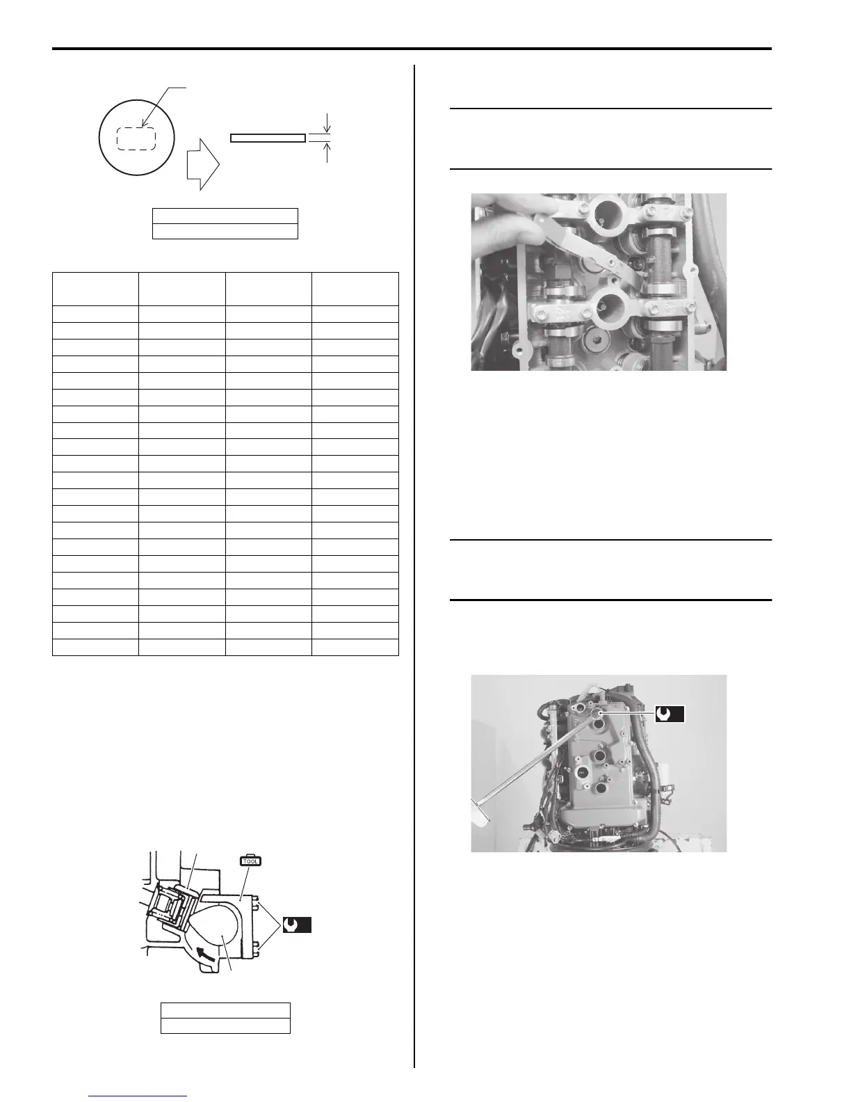
6) Install shim with the identification number facing
down (towards tappet).
7) Rotate crankshaft to open (lift up) valve.
8) Remove tappet holder (A) and tighten camshaft
housing bolts (a) to specified torque.
Tightening torque
Camshaft housing bolt (a): 11 N·m (1.1 kgf-m,
8.0 lbf-ft)
9) Recheck tappet clearance.
NOTE
After completing tappet clearance
adjustment and securing camshaft housing
bolts, inspect tappet clearance again.
10) After checking and adjusting all valves, reinstall parts
removed earlier.
Installation is reverse order of removal.
a) Cylinder Head Cover Installation.
• Install the cylinder head cover.
Refer to “Cylinder Head Cover Removal and
Installation” in Section 1D (Page 1D-2).
NOTE
Examine cylinder head cover gasket for
damage. Always replace gasket if sealing
performance is suspect.
Tightening torque
Cylinder head cover bolts (b): 11 N·m (1.1
kgf-m, 8.0 lbf-ft)
b) Final assembly check
• All parts removed have been returned to their
original positions.
• Check hose and wire routing.
Refer to “Wiring Harness Routing Diagram” in
Section 4A (Page 4A-4).
• Check oil leakage.
“C”: I.D No.
“a”: 2.50 mm
I.D. No.
Thickness
(mm)
I.D. No.
Thickness
(mm)
218 2.180 260 2.600
220 2.200 262 2.620
222 2.220 264 2.640
224 2.240 266 2.660
226 2.260 268 2.680
228 2.280 270 2.700
230 2.300 272 2.720
232 2.320 274 2.740
234 2.340 276 2.760
236 2.360 278 2.780
238 2.380 280 2.800
240 2.400 282 2.820
242 2.420 284 2.840
244 2.440 286 2.860
246 2.460 288 2.880
248 2.480 290 2.900
250 2.500 292 2.920
252 2.520 294 2.940
254 2.540 296 2.960
256 2.560 298 2.980
258 2.580 300 3.000
4. Tappet
5. Camshaft
(b)
 Loading...