1A-26 Engine Control:
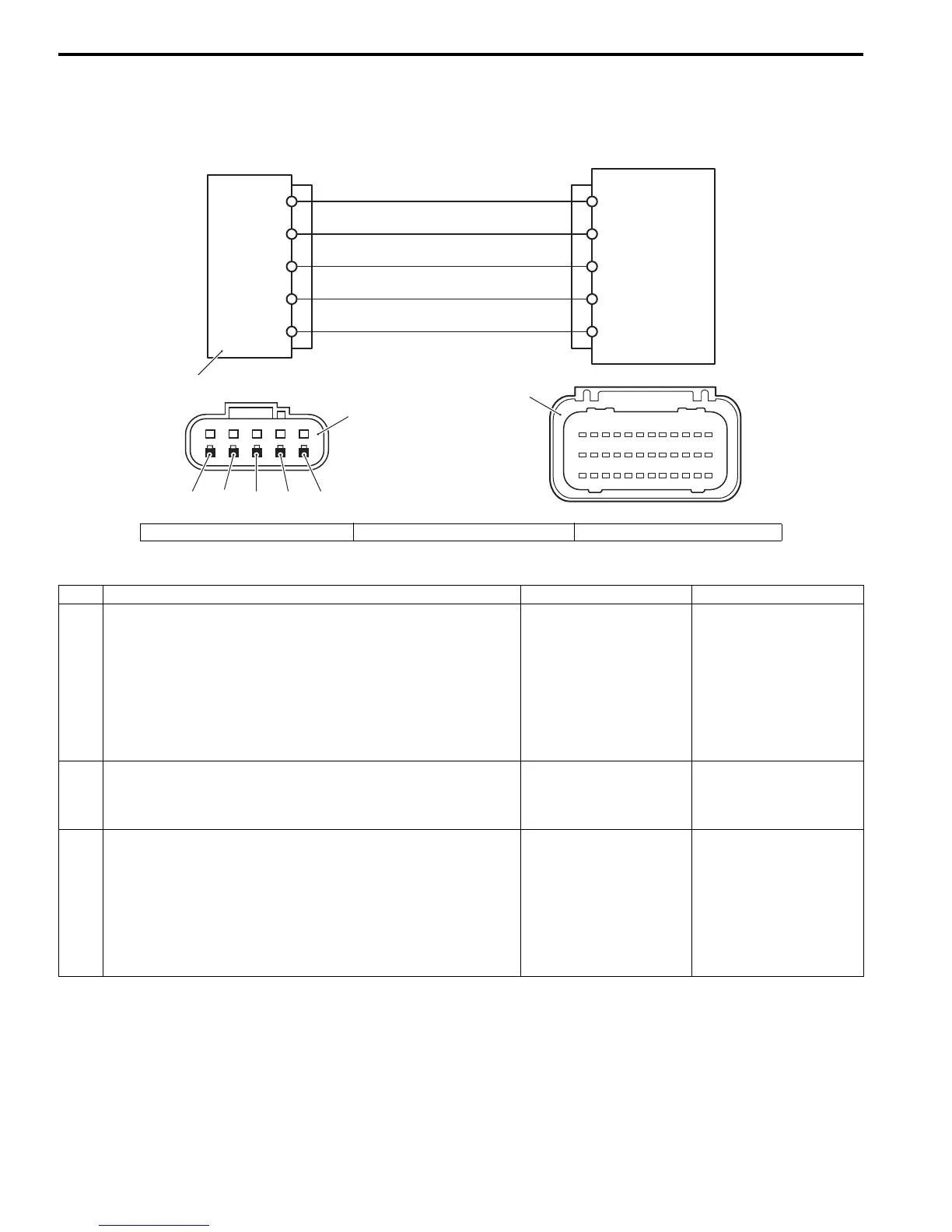
Self-Diagnostic Code “2 – 1” TPS (Throttle Position Sensor)
ZAJ6111104012
Wiring Diagram
Troubleshooting
ECM
Lg/B
123456789101112
13 14 15 16 17 18 19 20 21 22 23 24
25 26 27 28 29 30 31 32 33 34 35 36
8
32
25
6
33
W
B/W
Br/Y
R
B/W Br/Y RWLg/B
1
2
3
1. MAP sensor / TPS / IAT sensor 2. Sensor connector (harness side) 3. ECM connector (harness side)
Step Action Yes No
1 1) Turn the ignition switch “OFF”.
2) Check the TPS connector for loose or poor contacts.
If OK, then check the TPS lead wire continuity.
3) Disconnect the TPS connector at sensor.
4) Check the continuity between “Br/Y” wire terminal and
“R” wire terminal.
Is it no continuity?
Go to step 2. “R” wire shorted to “Br/
Y” wire.
2 1) With the ignition switch “ON”, check the voltage at the
“R” wire terminal of TPS and ground.
Is the voltage approx. 4 – 5 V?
Go to step 3. “R” wire open, “R” wire
shorted to ground circuit
or poor connection.
3 1) With the ignition switch “OFF”, disconnect ECM
connectors from ECM.
2) Check the continuity between “Br/Y” terminal of TPS
connector and No. 6 terminal of ECM connector.
Also check “B/W” terminal of TPS connector and No. 25
terminal of ECM connector.
Is it continuity?
Go to step 4. • “B/W” wire open.
• “Br/Y” wire open.



 To Next Page