Engine Electrical Devices: 1C-10
Installation
Installation is reverse order of removal with special
attention to the following steps.
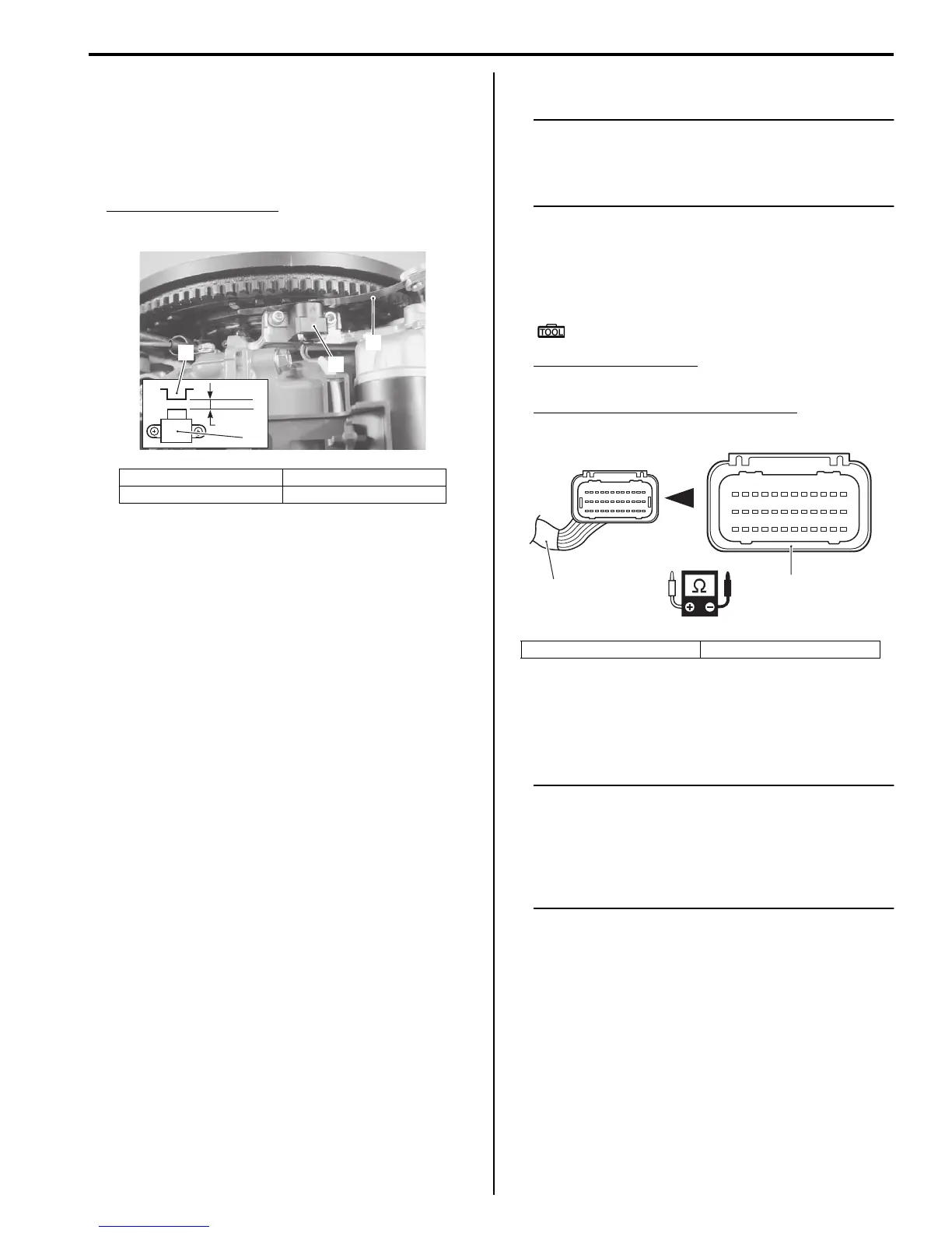
• Install CKP sensor with air gap of 0.75 mm between
sensor and reluctor bar on flywheel, then tighten
sensor mounting screws securely.
CKP sensor air gap “a”
0.75 mm (0.030 in.)
• Check to ensure that all removed parts are back in
original position.
• Check wire routing.
Refer to “Wiring Harness Routing Diagram” in Section
4A (Page 4A-4).
CKP Sensor Inspection
ZAJ6111306007
Inspect the CKP sensor.
Refer to “Resistance Check” (Page 1C-7).
IAT Sensor Inspection
ZAJ6111306009
NOTE
The IAT sensor is a thermistor type sensor,
which is very sensitive to temperature
change. Resistance will drop as temperature
goes up.
1) Disconnect wire harness connector at ECM.
2) Connect tester probes to No. 8 terminal and No. 25
terminal (wire harness side) and measure
resistance.
Special tool
: 09930–99320 (Digital tester)
Tester knob indication
Resistance (Ω)
IAT sensor resistance (temperature)
1.8 – 2.3 kΩ (25°C (77°F))
3) If out of specification, check wire harnesses for open
and short.
If wire harnesses are in good condition, replace
throttle body assembly and recheck.
NOTE
MAP sensor / TPS / IAT sensor are combined
into one unit that is installed on top of the
throttle body. Never loosen the screws
securing TPS. TPS position has been
adjusted the factory and must not be
changed.
1. CKP sensor 3. Thickness gauge
2. Reluctor bar
1. Engine main wire harness 2. Black connector
123456789101112
13 14 15 16 17 18 19 20 21 22 23 24
25 26 27 28 29 30 31 32 33 34 35 36
1
2