4E-40 ABS:
Installation
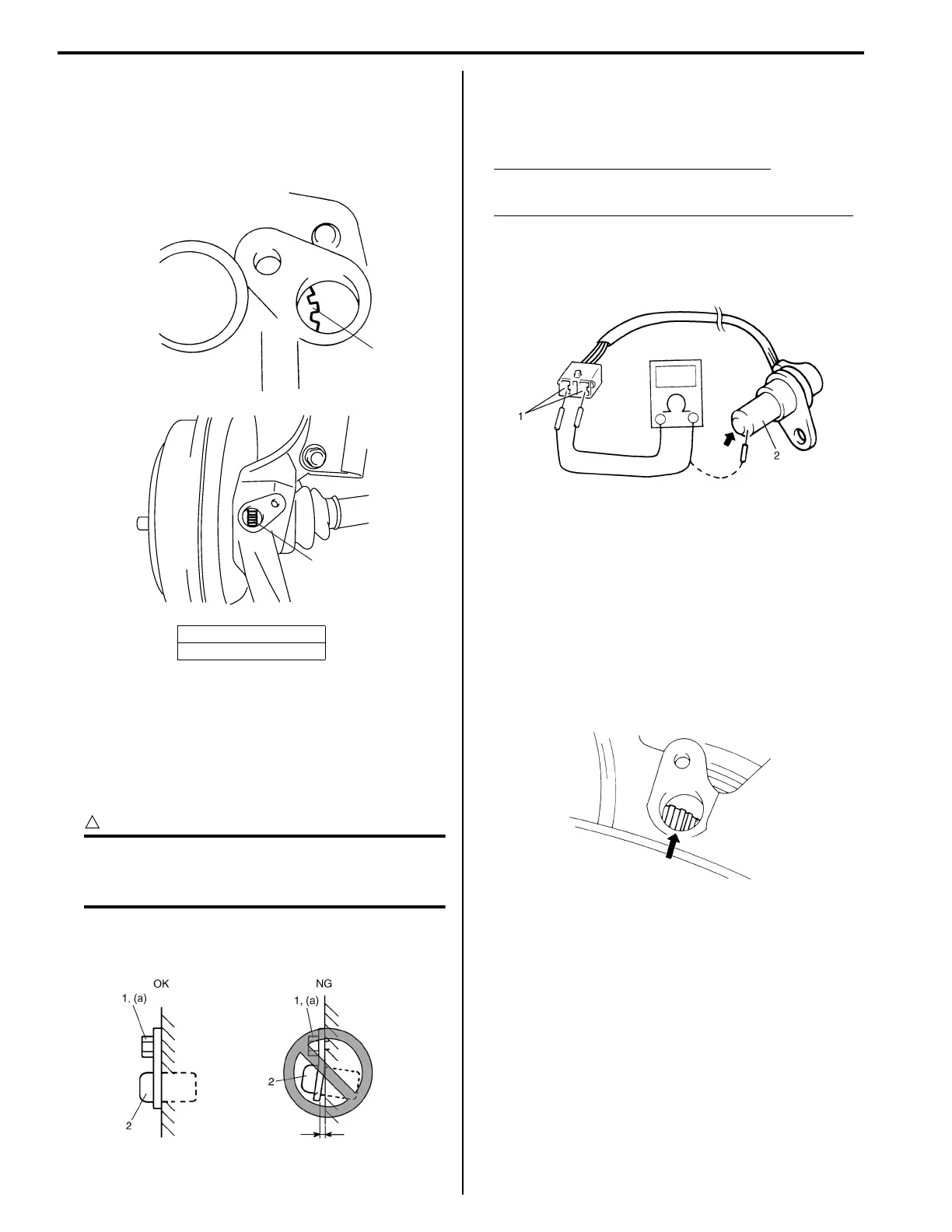
Reverse removal procedure for installation noting the
following.
• Check that no foreign material is attached to sensor
and ring (1).
• Be sure to install wheel speed sensor (2) and its bolt
at the correct (upper) position as shown in figure.
Tighten sensor bolt (1) to specified torque.
Tightening torque
Rear wheel speed sensor bolt ((a)): 23 N·m (2.3
kgf-m, 17.0 lb-ft)
CAUTION
!
Do not pull or twist wire harness more than
necessary when installing rear wheel speed
sensor.
• Check that there is no clearance between sensor and
knuckle.
Rear Wheel Speed Sensor Inspection
S3RH0A4506010
• Check sensor for damage.
• Measure resistance of sensor.
Between both terminals (1) of sensor
1.2 – 1.6 kΩ at 20 °C (68 °F)
Between sensor terminal (1) and sensor body (2)
Infinity (∞)
If the check result is not as specified and any
malcondition is found, replace.
Front Wheel Speed Sensor Ring On-Vehicle
Inspection
S3RH0A4506011
• Check ring for being missing, damaged or deformed.
• Turn drive shaft and check if ring rotation is free from
eccentricity and looseness.
• Check that no foreign material is attached.
If any faulty is found, repair or replace. Refer to “Front
Drive Shaft Assembly Removal and Installation in
Section 3A”.
[A]: For 2WD vehicle
[B]: For 4WD vehicle
[A]
[B]
1
1
I3RH0A450025-01
I2RH01450060-01
I3RH01450052-01
I2RH01450053-01
 Loading...