8B-29 Air Bag System:
NOTE
Upon completion of inspection and repair work, perform the following items.
• Reconnect all air bag system components, ensure all components are properly mounted.
• Repeat “Air Bag Diagnostic System Check” to confirm that the trouble has been corrected.
DTC B1015: Passenger Air Bag Initiator Circuit Resistance High
S3RH0A8204014
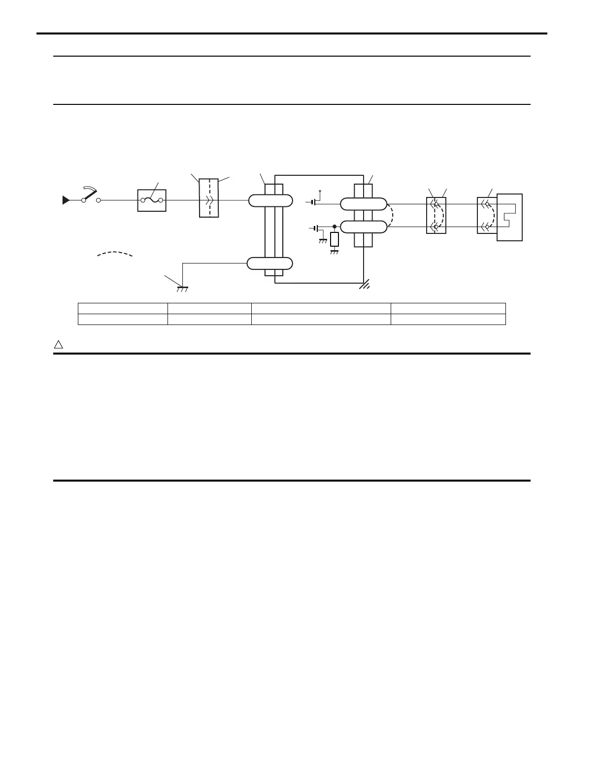
Wiring Diagram
CAUTION
!
• Be sure to perform “Air Bag Diagnostic System Check” before starting diagnosis according to flow
table.
• When measurement of resistance or voltage is required in this table, use a specified digital
multimeter (Refer to “Special Tool”.) along with a correct terminal adaptor from special tool
(Connector test adapter kit).
• When a check for proper connection is required, refer to “Inspection of Intermittents and Poor
Connections”.
• If there is open circuit in the air bag wire harness, connector or terminal is found damaged, replace
the wire harness, connector and terminal as an assembly.
DTC Will Set when
The combined resistance of the passenger air bag (inflator) module, harness wiring and connector terminal contact is
above a specified value for specified time.
Flow Test Description
Step 1: Check whether malfunction is in passenger air bag (inflator) module.
Step 2: Check passenger air bag (inflator) module initiator circuit in air bag harness.
1
2
REDGRN
RED
3
6
BLK
“L70”
L70-32
L70-31
4
“G14”
“L80”
YEL/GRN
YEL
“L38”“L72”
“L35”
“L70”
5
[A]
+12V
L70-24
L70-23
I3RH0A820021-02
[A]: Shorting bar 2. Ignition switch 4. SDM 6. Ground for air bag system
1. From main fuse 3. “AIR BAG” fuse 5. Passenger air bag (inflator) module
 Loading...