Heater and Ventilation: 7A-3
Schematic and Routing Diagram
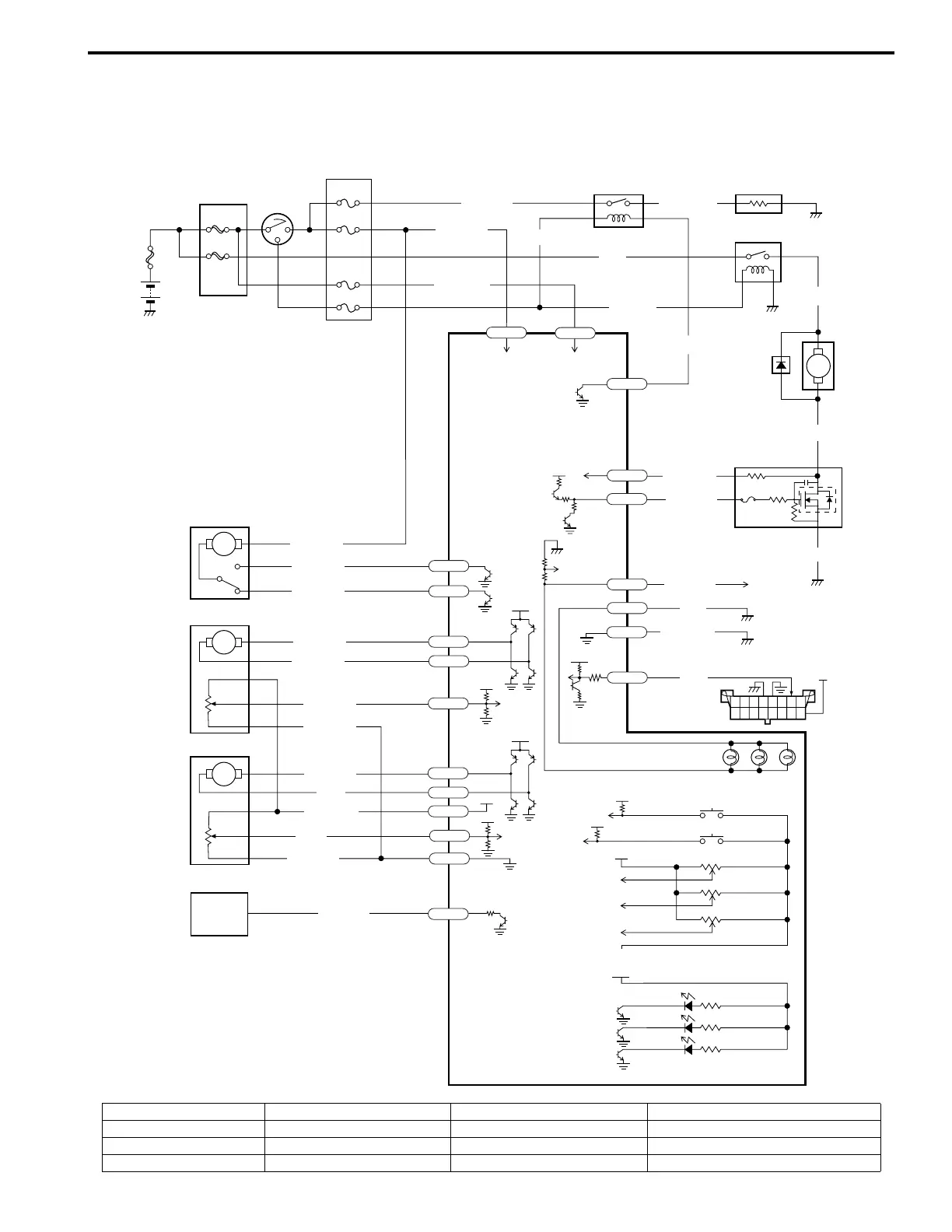
Heater and Ventilation Wiring Circuit Diagram
S3RH0A7102001
60A
30A
20A
10A
15A
10A
M
12V
12V
5V
+BB
5V
5V
WHT/RED
PPL/WHT
BLU/WHT
BLU/YEL
RED/YEL
BLU/RED
BLK
BLK
RED/BLK
M
M
M
12V
12V
5V
5V
5V
YEL/RED
WHT/BLU
RED/WHT
WHT
BLK/RED
BLK/RED
YEL/GRN
GRY/RED
GRY/BLK
GRY/BLU
GRY
RED/BLK
G77-9
G77-28
G77-26
G77-20
G77-19
G77-12
G77-18
G77-17
G77-22
G77-21
G77-3
G77-6
G77-5
G77-14
G77-13
BLU/WHT
RED/WHT
BLU
LT GRN
BLU/YEL
LT GRN
G77-7
G77-25
BLK/ORN
BLU
G77-15
G77-16
12V
BLU/BLK
G77-2
1
3
2
4
5
6
7
8
13
9
10
11
12
14
a
I3RH0A710004-01
1. Main fuse box 5. Rear defogger 9. Air intake control actuator 13. HVAC control module
2. Ignition switch 6. Blower motor relay 10. Air flow control actuator 14. DLC
3. Circuit fuse box 7. Blower motor 11. Temperature control actuator a: Lighting switch or DRL controller
4. Rear defogger relay 8. Blower motor controller 12. ECM
 Loading...