Air Conditioning System: Automatic Type 7B-56
DTC B1503 (No.03): A/C Evaporator Air Temperature Sensor and/or its Circuit Malfunction
S3RH0A7224013
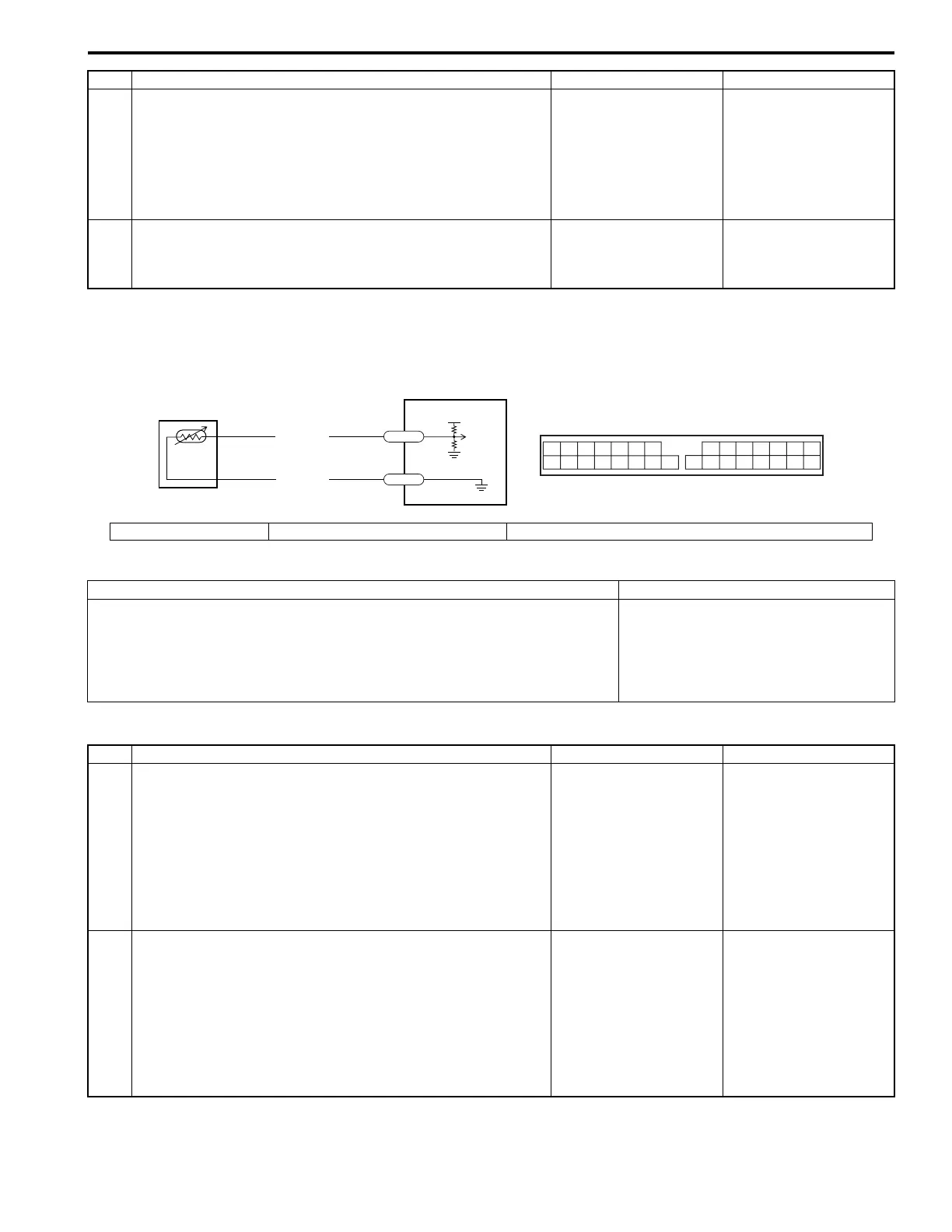
Wiring Diagram
DTC Detecting Condition and Trouble Area
DTC Troubleshooting
4 1) With ignition switch ON position, check voltage between
“ORN/BLK” wire terminal and “BLK/RED” wire terminal
at inside air temperature sensor connector.
Is voltage about 3.5 V?
Go to Step 5. “BLK/RED” wire open,
poor connection of
“BLK/RED” wire
terminal at HVAC
control module
connector, and/or HVAC
control module faulty.
5 1) Check inside air temperature sensor referring to “Inside
Air Temperature Sensor Inspection”.
Is inside air temperature sensor normal?
HVAC control module
faulty.
Inside air temperature
sensor faulty.
Step Action Yes No
5V
WHT/BLK
BLK/RED
G77-30
G77-9
2
1
3
912
I3RH0A722009-01
1. HVAC control module 2. A/C evaporator air temperature sensor 3. HVAC control module connector “G77” (viewed from harness side)
DTC Detecting Condition Trouble Area
• Signal from A/C evaporator temperature sensor is less than the specified
(0.7 V). (A/C evaporator temperature is less than –70 °C, –94 °F.)
• Signal from A/C evaporator temperature sensor is more than the specified
(3.3 V). (A/C evaporator temperature is more than 107 °C, 224.6 °F. )
• “WHT/BLK” and/or “BLK/RED” wire
faulty
• A/C evaporator air temperature
sensor faulty
• HVAC control module faulty
Step Action Yes No
1 1) Turn ignition switch OFF, and then disconnect A/C
evaporator temperature sensor connector referring to “A/
C Evaporator Outlet Air Temperature Sensor Removal
and Installation”.
2) Turn ignition switch ON, and then check voltage
between “WHT/BLK” wire terminal at A/C evaporator
temperature sensor connector and body ground.
Is voltage about 3.5 V?
Go to Step 4. Go to Step 2.
2 1) Turn ignition switch OFF, and then disconnect HVAC
control module connector referring to “HVAC Control
Module Removal and Installation in Section 7A”.
2) Check resistance between “WHT/BLK” wire terminal at
A/C evaporator temperature sensor connector and
“WHT/BLK” wire terminal at HVAC control module
connector.
Is resistance less than 1 M
Ω
?
Go to Step 3. “WHT/BLK” wire open
or high resistance.
 Loading...