8B-35 Air Bag System:
DTC B1018: Passenger Air Bag Initiator Circuit Short to Ground
S3RH0A8204016
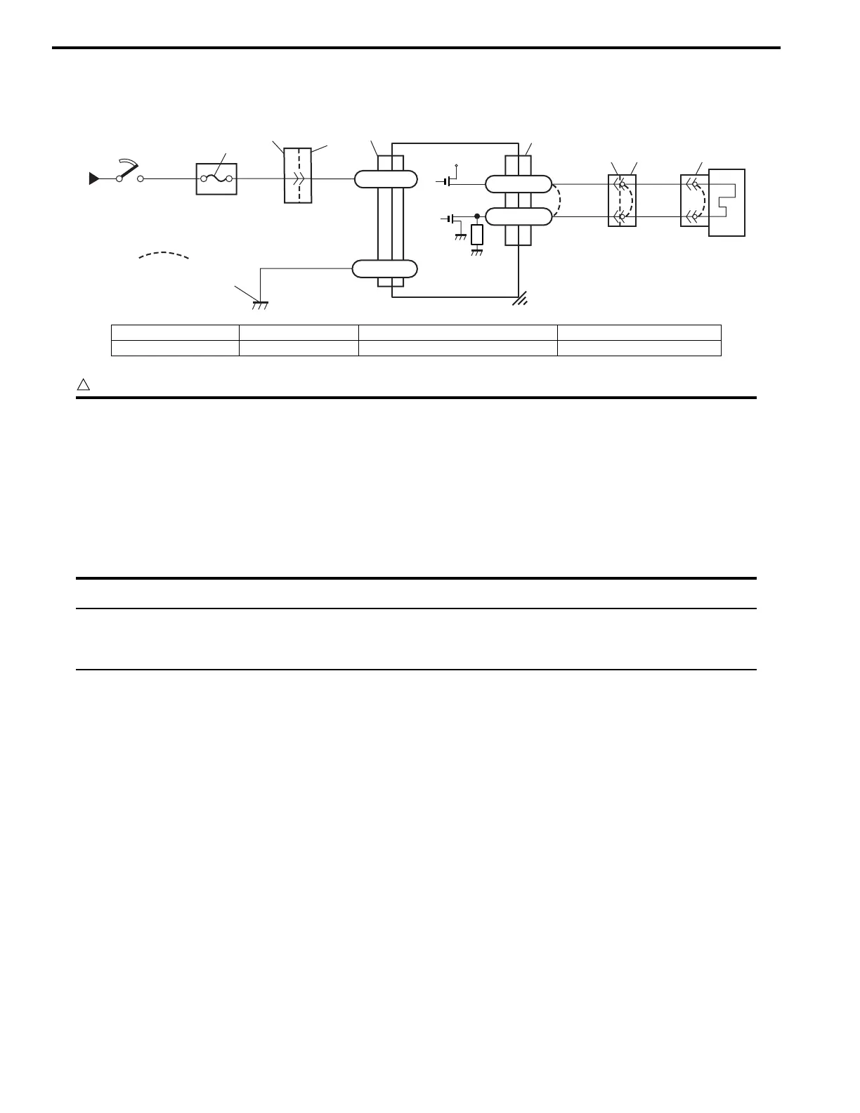
Wiring Diagram
CAUTION
!
• Be sure to perform “Air Bag Diagnostic System Check” before starting diagnosis according to flow
table.
• When measurement of resistance or voltage is required in this table, use a specified digital
multimeter (Refer to “Special Tool”.) along with a correct terminal adaptor from special tool
(Connector test adapter kit).
• When a check for proper connection is required, refer to “Inspection of Intermittents and Poor
Connections”.
• If there is open circuit in the air bag wire harness, connector or terminal is found damaged, replace
the wire harness, connector and terminal as an assembly.
NOTE
If vehicle is equipped with driver or passenger side air bag ON-OFF switch, perform “Air Bag
Diagnostic System Check Flow” with disconnecting air bag ON-OFF switch from air bag circuit. And if
this DTC is not detected under the condition, replace air bag ON-OFF switch and recheck.
DTC Will Set when
The voltage measured at passenger air bag initiator circuit is below a specified value for specified time.
Flow Test Description
Step 1: Check whether malfunction is in passenger air bag (inflator) module.
Step 2: Check passenger air bag (inflator) module initiator circuit in air bag harness.
1
2
REDGRN
RED
3
6
BLK
“L70”
L70-32
L70-31
4
“G14”
“L80”
YEL/GRN
YEL
“L38”“L72”
“L35”
“L70”
5
[A]
+12V
L70-24
L70-23
I3RH0A820021-02
[A]: Shorting bar 2. Ignition switch 4. SDM 6. Ground for air bag system
1. From main fuse 3. “AIR BAG” fuse 5. Passenger air bag (inflator) module
 Loading...