8B-21 Air Bag System:
NOTE
Upon completion of inspection and repair work, perform the following items.
• Reconnect all air bag system components, ensure all components are properly mounted.
• Repeat “Air Bag Diagnostic System Check” to confirm that the trouble has been corrected.
“AIR BAG” Warning Lamp Does Not Come ON
S3RH0A8204010
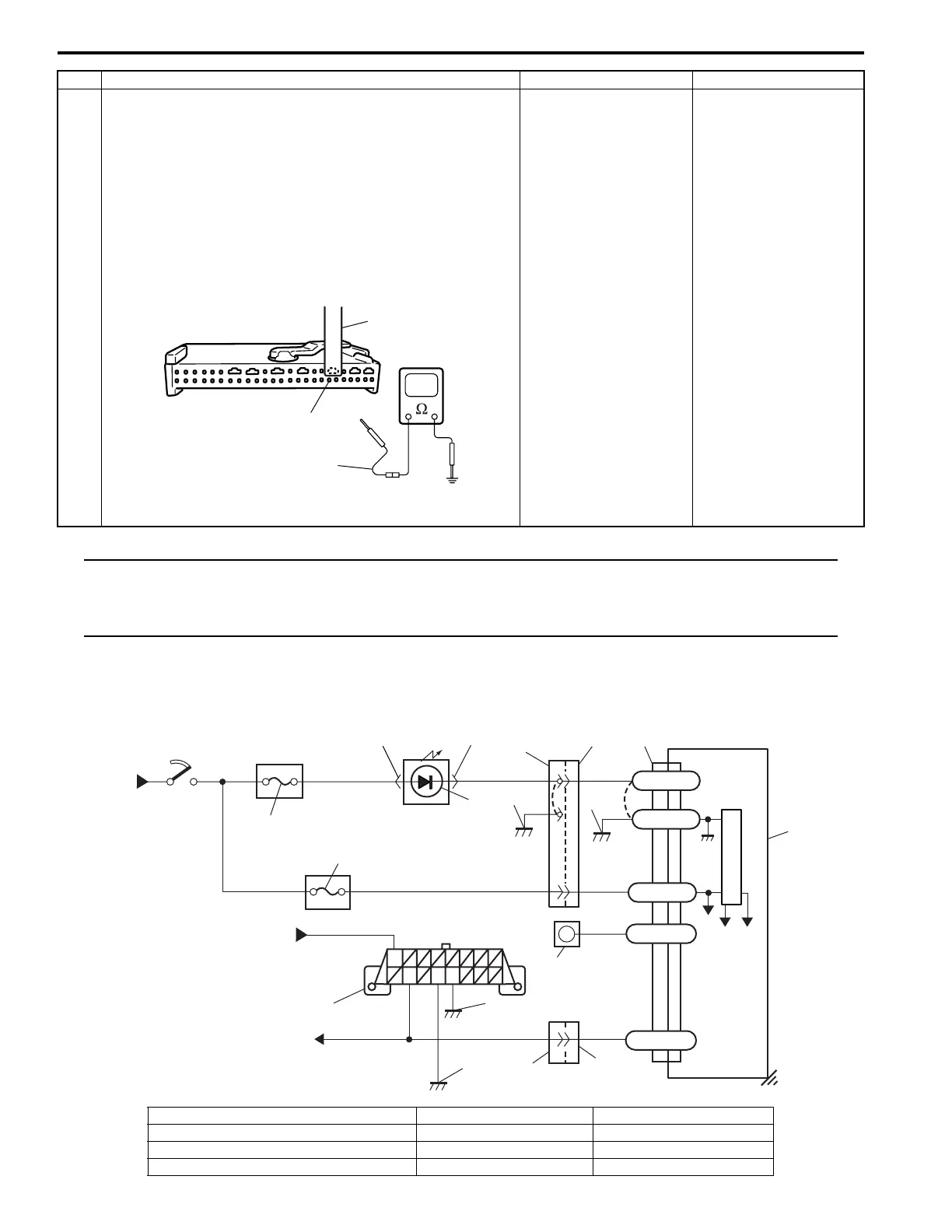
Wiring Diagram
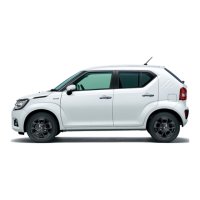
5 1) Disconnect connector “G20” from combination meter
referring to “Combination Meter Circuit Diagram in
Section 9C”.
2) Release shorting bar of “L70-30” terminal inserting
release tool (A).
3) Measure resistance between “L70-30” terminal and body
ground.
Special tool
(A): 09932-76010
Is resistance infinity?
Substitute a known-
good SDM and recheck.
Clear up short circuit
between “YEL/RED”
wire and ground.
Step Action Yes No
(A)
“L70-30”
(A)
I2RH01820014-01
1
2
3
4
GRN
GRN
BLK/RED
YEL/RED
YEL/RED
RED
RED
BLU
BLU
5
8
9
PPL
“L79”
“L83”
“G46”
“L70”
L70-32
L70-28
L70-8
6
“G14”
“G20”
“L80”
10
+30V+5V
L70-30
BLK
BLK
L70-31
11
“G21”
1
BLK
BLK/ORN
WHT/RED
BLU
7
11
12
I3RH0A820018-01
1. From main fuse 5. “AIR BAG” fuse 9. “AIR BAG” monitor coupler
2. Ignition switch 6. SDM 10. Ground for air bag system
3. “METER” fuse 7. Data link connector (DLC) 11. Ground on body
4. “AIR BAG” warning lamp in combination meter 8. To other control module 12. Ground on Engine block
 Loading...