GB.GOLDSK509.091101
We reserve the right to alter specifications without notice.
www.swegon.com 63
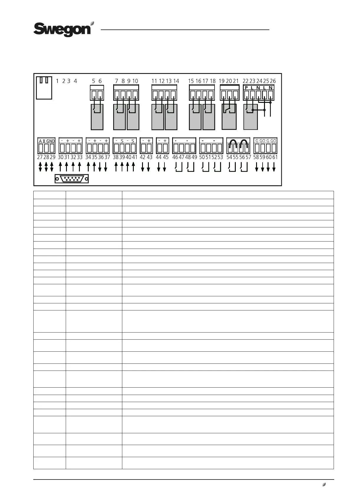
19.5 Terminal Connections, Sizes 04-80
Digital inputs,
terminals 46-57,
are of low voltage
type.
Analogue inputs,
terminals 30-35,
have input imped-
ance 66 kΩ.
Terminals Function Remarks
1 and 2 Not used
3 and 4 Not used
5 and 6 Circulation pump, heating Independent contacts, max 12A/AC1, 5A/AC3, 250VAC. Close when heating is needed.
7 and 8 Cooling, on/off, step 1 Independent contacts, max 12A/AC1, 5A/AC3, 250VAC. Close when cooling is needed.
9 and 10 Cooling, on/off, step 2 Independent contacts, max 12A/AC1, 5A/AC3, 250VAC. Close when cooling is needed.
11 and 12 In-op. indication, low speed Independent contacts, max 12A/AC1, 5A/AC3, 250VAC. Close when the fans operate at low speed.
13 and 14 In-op. indication, high speed Independent contacts, max 12A/AC1, 5A/AC3, 250VAC. Close when the fans operate at high speed.
15 and 16 Group alarm A (1) Independent contacts, max 12A/AC1, 5A/AC3, 250VAC. Closes or opens (setting) if an A alarm trips.
17 and 18 Group alarm B (2) Independent contacts, max 12A/AC1, 5A/AC3, 250VAC. Closes or opens (setting) if an B alarm trips.
19 , 20 and 21 In-operation indication Independent contacts, max 12A/AC1, 5A/AC3, 250VAC. 19 NC, 20 C, 21 NO. Close when AHU is in operation.
22 , 23 and 24 Damper control 230VAC. 22: controlled phase, 23: fixed phase, 24: zero conductor. 22 is energized while the AHU operations.
25 and 26 Control voltage, output Control voltage 230VAC. Max load 1.5A. Interrupted by safety switch and burdens the supply voltage fuse.
27, 28 and 29 Connections for EIA-485
network
27 communication connection A/RT+, 28 communication connection B/RT-, 29 GND/COM.
30 and 31 Supply air boost Input for 0-10VDC. Input signal acts upon the supply air flow/pressure setpoint.
32 and 33 Extract air boost Input for 0-10VDC. Input signal acts upon the extract air flow/pressure setpoint.
34 and 35 External 0-10VDC input. Acts on the supply air setpoint if the AHU is operating in the supply air regulation mode. Acts
on the extract air setpoint if the AHU is operating in the extract air regulation mode. Effect: ±5°C. If the AHU
is operating in the ERS regulation mode, it acts on the EA/SA differential. The differential cannot be <0°C. The
EA/SA differential decreases on an increasing input signal. Can be activated from the hand-held micro terminal.
36 and 37 Reference voltage Output for constant 10VDC. Max. permissible load: 2mA.
38 and 39 External outdoor
temperature sensor
38 GND, 39 signal. Connection for externally mounted digital outdoor temperature sensor.
40 and 41 External EA/room
temperature sensor
40 GND, 41 signal. Connection for externally mounted digital extract air/room temperature sensor.
42 and 43 Variable control, cooling Output for cooling, 0-10VDC. Max. permissible load: 2mA at 10VDC.
44 and 45 Control: extra control
sequence/recirculation
damper
Use of the control output steered by the function selected in the hand-held micro terminal. Max.
permissible load: 2mA at 10VDC.
46 and 47 External low speed External contact function. Overrides the switch clock from stop to low speed operation.
48 and 49 External high speed External contact function. Overrides the switch clock from stop or low speed to high speed operation.
50 and 51 External alarm 1 External contact function. Optional normally open/normally closed. External alarm is available in the GOLD.
52 and 53 External alarm 2 External contact function. Optional normally open/normally closed. External alarm is available in the GOLD.
54 and 55 External fire/smoke
function
External fire and smoke function. On delivery, this function is fitted with a jumper. The contacts connected
between 54 and 55 are closed while the unit is operating. If they open, the function will trip and initiate an
alarm.
56 and 57 External stop Stops the AHU via normally-closed contacts. Fitted with jumper on delivery. AHU operation presupposes
connection between 56 and 57. If the connection is interrupted, the AHU will stop.
58 and 59 Control voltage 24VAC control voltage. Terminals 58-61 can bear a combined total load of max 16VA all total. Can be
interrupted by safety switch.
60 and 61 Control voltage 24VAC control voltage. Terminals 58-61 can bear a combined total load of max 16VA all total. Can be
interrupted by safety switch.