机床产品/Machine Tool Products
–
22/220 Series Controller Application Manual
Pitch Error Compensation–27
•
•
•
•
•
•
•
8 Pitch Error Compensation
8.1 Preface
Pitch error is caused by manufacturing error of ball screws which leads to the inconsistency between command and
actual motion of the bench.
Because the error of each ball screw is fixed, it can be measured by instruments, setup in controller parameters, and
be compensated during machining.
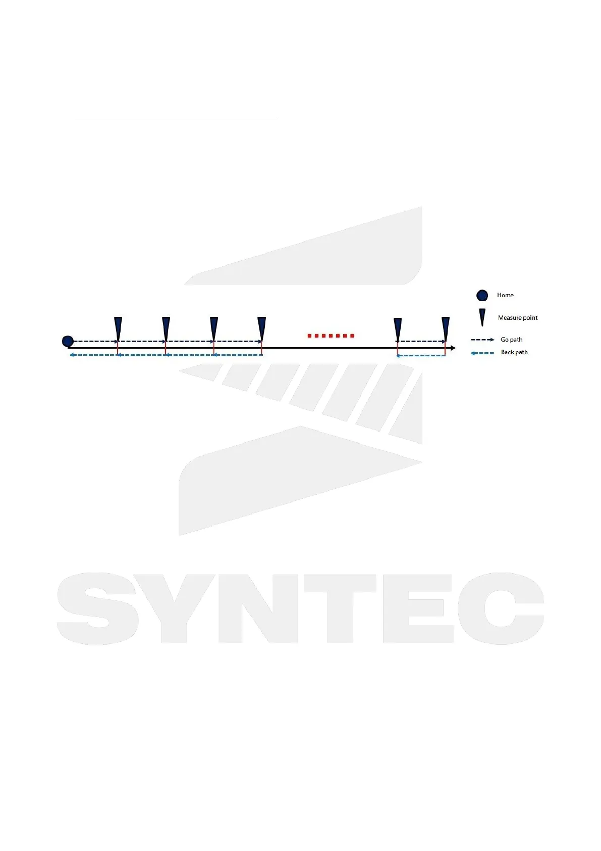
The diagram below describes for pitch error measurement. Normally a laser interferometer is used for position
measurement,and needs an NC program for fix-increment movement.
After the measurement completed, the pitch error (the difference between machine coordinate and the actual
position) of each measurement point can be calculated and thenused for compensation.
8.2 Path
8 key, 5 key : F10 Next→ F3 Param.→ F4 Comp. Param.→F1 Pitch Table
8.3 Specifications
After Homing (zero point searching) completed, the pitch compensation is enabled.
Compensation table has two directions: positive and negative. Themechanical coordinate changes from low
to high is positive; and from high to low is negative.
There are two types for compensation: uni-directional and bi-directionals. Their descriptions are below:
When axis moves to positive/negative direction (or motor rotates CW/CCW), the screw and
transmission interfaces are usually different due to production and assembly tolerance. Therefore
the positive & negative movement can have different pitch error.
After the pitch error measurement, most of the result are similar to the left diagram. The two lines
have same trends (Note: the offset of the two lines is backlash). In this case, it is suggested to just use
uni-directional compensation.
If the measurement result is similar to the right diagram, it indicates that the ball screw has precision
or assembly problem. In this case, it is suggested to use bi-directional compensation, or re-check
 Loading...