TP9100 Service Manual Frequency Synthesizer Fault Finding 163
© Tait Electronics Limited May 2005
9.2 Power Supplies
Introduction First check that a power supply is not the cause of the fault. There are four
power supplies for the frequency synthesizer:
■ Task 3: 14V DC supply from SMPS (VCL SUPPLY)
■ Task 4: 5V DC supply from 7V5 LINK in power supply circuitry (+5V0 AN)
■ Task 5: 4.3V DC supply following filtering of 5V AN (+4V3 DEC)
■ Task 6: 3V DC supply from 3V regulator in power supply circuitry
(+3
V0 AN)
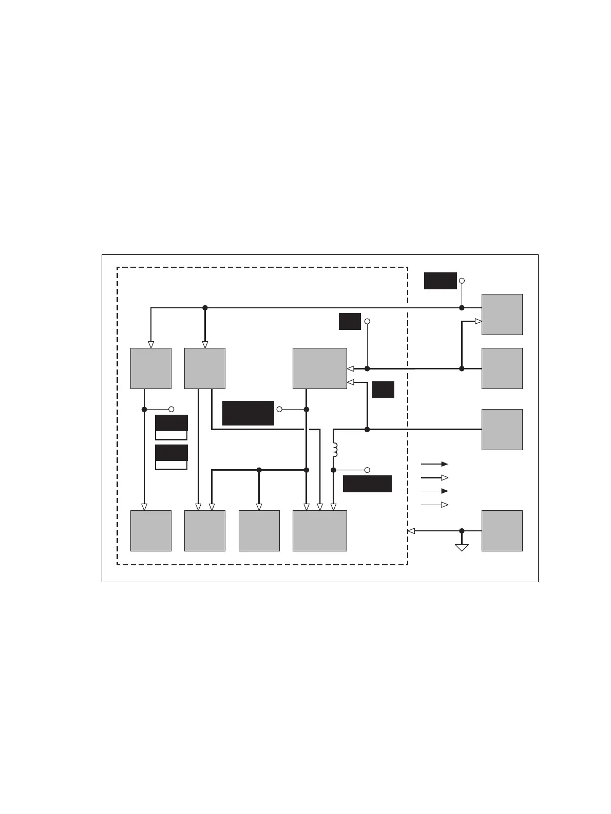
The measurement points for diagnosing faults in the power supplies are
summarized in Figure 9.1.
Figure 9.1 Measurement points for the synthesizer power supply circuitry
PIN 4 OF
IC601
R533
PINS 7 AND 15
OF IC503
SIGNAL TYPES
RF
ANALOG
CLOCK
DIGITAL
PLL
SMPS
LOOP
FILTER
AND
SUMMER
FILTERING
OF SUPPLY
FOR PLL
AND LOOP
FILTER
FILTERING
OF SUPPLY
FOR VCO
CIRCUITRY
3V
SUPPLY
VCO
CIRCUITRY
FREQUENCY
SYNTHESIZER
INTERFACE
CIRCUITRY
INVERTER
JUNCTION OF
C531 AND R530
D512
JUNCTION OF
C531 AND R530
D512
+3V0 AN
L506
7V5
SUPPLY
5V
SUPPLY
AGND
+7V5 LINK
+5V0 AN
VCL SUPPLY+4V3 DEC
PIN 1 OF
Q508
B1
PIN 4 OF
Q508
H5/H6
Q500

 Loading...


