TP9100 Service Manual Transmitter Fault Finding 239
© Tait Electronics Limited May 2005
10.4 RF Signal Path
Introduction The RF signal path extends from the output of the frequency synthesizer to
the LPF. This section of circuitry will require investigation either following
certain checks in “Transmitter RF Power” or if the biasing checks of
“Biasing of PA Driver and PA” reveal no fault. The procedure is divided
into nine tasks grouped as follows:
■ Task 18 to Task 20: initial RF signal path
■ Ta s k 21 a n d Ta s k 22: P I N swi t c h
■ Ta s k 23 : LPF
The initial signal path includes the exciter and PA driver. The PIN switch,
and LPF make up the final signal path. The measurement points for
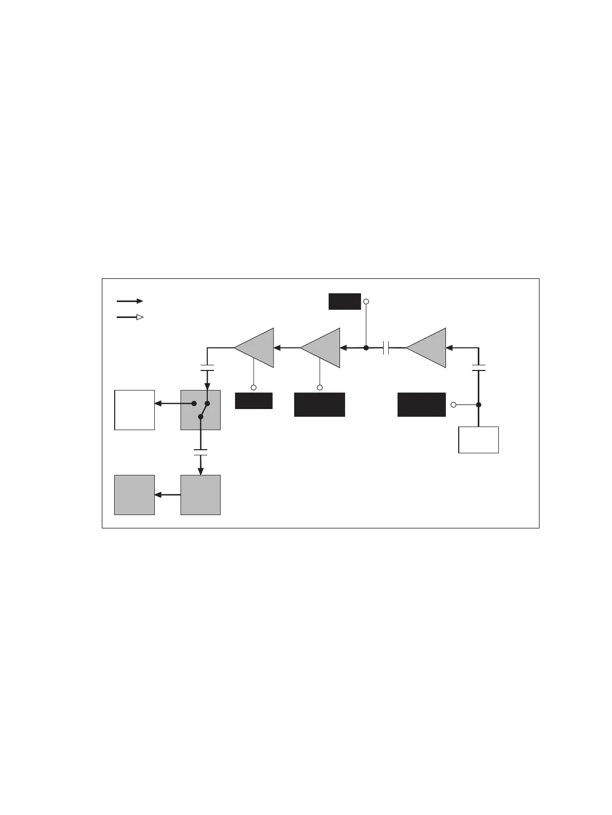
diagnosing faults in the signal path are summarised in Figure 10.9.
Figure 10.9 Measurement points for diagnosing faults in the RF signal path
RF
Connector
Receiver
LPF
PAs
PIN
switch
Driver Exciter
Signal types
RF
analog
Synthesizer
Output
SYN TX LO
PA driver
output at
drain of Q103
Exciter
Output
Gates of
Q106
C146 (B1)
C110 (H5, H6)
C138 (B1)
C125 (H5/H6)
C151
C160
Frequency
Synthesizer