208 Frequency Synthesizer Fault Finding TP9100 Service Manual
© Tait Electronics Limited May 2005
9.9 VCXO and VCTCXO Outputs
Task 35 —
VCXO Output
If the 3V power supply is not faulty, check the VCXO output as follows:
1. Use an oscilloscope probe to check the VCXO output at C536 —
probe the via next to C536 (see Figure 9.19). The signal should be:
2. If the signal is correct, go to Ta s k 3 6
. If it is not, go to Step 3.
3. The VCXO circuitry under the
VCXO BOT can is faulty. Remove the
VCXO BOT can.
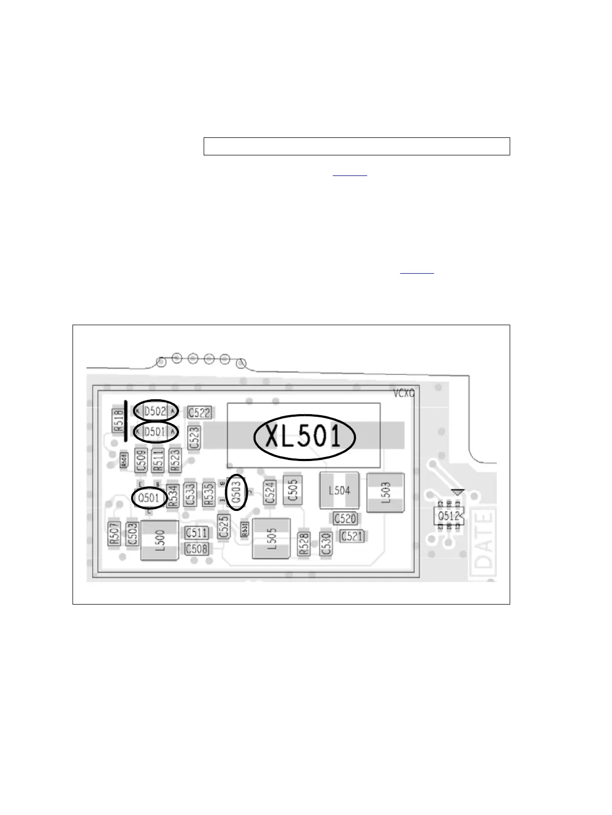
4. Locate and repair the fault in the VCXO (Q501, Q503, XL501 and
associated components) (see Figure 9.20).
5. Confirm the removal of the fault and go to Tas k 36
. If the repair
failed, replace the main board and go to “Final Tasks” on page 134.
VCXO output at C536: sine wave of 1.1 ± 0.2V
pp
on 1.4 ± 0.2V DC
Figure 9.20 FCL circuitry under the VCXO BOT can (bottom side)