220 Transmitter Fault Finding TP9100 Service Manual
© Tait Electronics Limited May 2005
10.1 Power Supplies
Introduction First check that a power supply is not the cause of the fault. There are two
power supplies for the transmitter:
■ Task 1: 7.5VDC supply from power connector (+7V5 BATT)
■ Task 2: 5VDC supply from 9V regulator in PSU module (+5V0 TX)
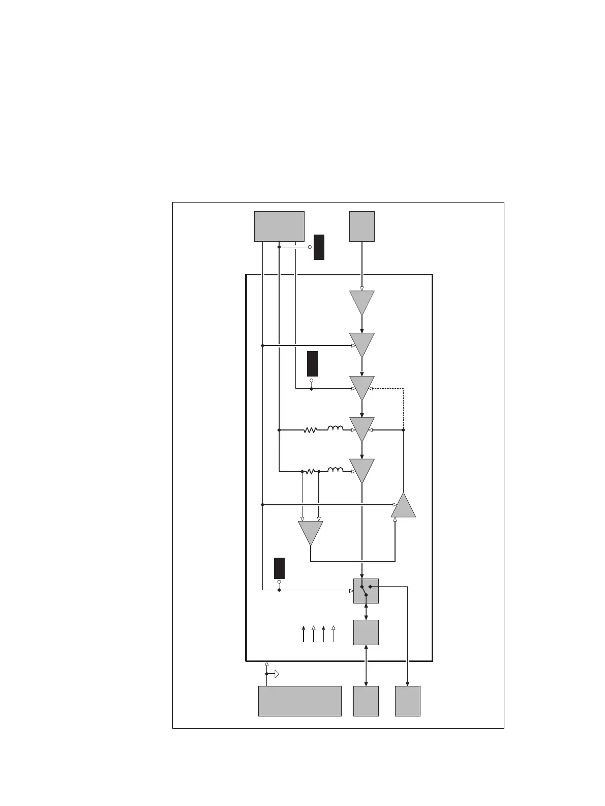
The power supplies distribution is summarized in Figure 10.1.
Figure 10.1 Measurement and test points for diagnosing faults involving
the power supplies for the transmitter
RF
Connector
Receiver
LPF
PA
Power
Control
PIN
Switch
Driver Exciter
TX RX RF
Transmitter
+5V TX
+7V5 LINK
SYN TX LO
Power
Supply
Frequency
Synthesizer
Signal Types:
RF
analog
clock
digital
Interfaces
AGND
Buffer
R150
Current
Sensing
PA
Difference
Amplifier
Pre-
Driver
+7V5 BATT
+7V5 LINK
L115
R150/R124/
R197
Current
Limiting
L111
(UHF only)
+5V TX
+7V5 BATT

 Loading...


