EasyManua.ls Logo

Tait TP9100 Service Manual

Tait TP9100
326 pages
To Next Page IconTo Next Page
Page #1 background imageLoading...
Page #1 background image
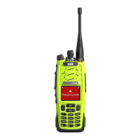
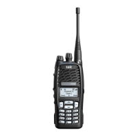
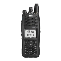
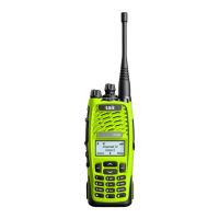
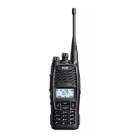
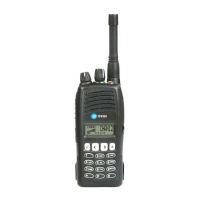
TP9100 portables
Service Manual
MPA-00005-01
Issue 1.00
May 2005

Table of Contents

Other manuals for Tait TP9100

Questions and Answers:

Tait TP9100 Specifications

General IconGeneral
Channel Spacing12.5 kHz, 20 kHz, 25 kHz
Digital ProtocolDMR Tier II
Operating Temperature-30°C to +60°C
Frequency Range400-470 MHz
Power Output5W
Audio Output1W
Operating Voltage7.4 V (nominal)
RF Output Power5W

Summary

Preface and Manual Overview

Chapter 1: Description of the Radio

Chapter 2: Radio Description and Architecture

Hardware and Software Architecture

Explains the radio's hardware architecture, including main board and front-panel interface, and its software modules.

Frequency Synthesizer and Control Loops

Explains the frequency synthesizer, including the FCL, RF PLL, and their operation for frequency generation and control.

Chapter 3: Circuit Descriptions

Transmitter Circuitry

Describes the exciter, driver, power amplifier, and power control loop of the transmitter.

Receiver Circuitry

Details the receiver's triple-conversion superheterodyne type, including front-end, mixers, and IF stages.

Frequency Synthesizer Circuitry

Explains the frequency synthesizer, its power supplies, and key components like VCOs, PLL, and loop filters.

CODEC and Audio Circuitry

Describes the CODEC devices and audio circuitry, covering analog-to-digital conversion and audio signal processing.

Power Supply Circuitry

Details the internal power supplies, including regulators and SMPS, used by the radio's various modules.

Chapter 4: General Information for Servicing

Tools, Equipment, and Spares

Lists required tools, test equipment, and describes the service kit contents for radio servicing.

Servicing Precautions

Outlines essential precautions for servicing, including mechanical, compliance, anti-static, and transmitter safety.

Test Equipment Setup

Provides instructions on setting up test equipment and connecting it to the radio for servicing.

Computer-Controlled Test Mode (CCTM)

Describes how to enter and use the CCTM for radio diagnostics and parameter adjustment.

Chapter 5: Disassembly and Reassembly

Radio Disassembly Procedures

Step-by-step instructions for disassembling the radio, including knobs, chassis, and main board.

Radio Reassembly Procedures

Step-by-step instructions for reassembling the radio, including fitting components like the speaker and main board.

Chapter 6: Servicing Procedures

Initial Servicing Tasks

Outlines the initial tasks required for all radios, including administration, inspection, and configuration checks.

Transmit and Receive Function Checks

Guides on checking transmit and receive functions, including synthesizer lock and power levels.

Final Tasks After Repair

Describes the final steps after repair, including enabling software features, final inspection, testing, and administration.

Chapter 7: Interface Fault Finding

Chapter 8: Power Supply Fault Finding

Initial Power Supply Checks

Covers initial checks of required power supplies (+3V3, +1V8, +1V5) for radio operation.

Checking +3V3 and +1V5 SMPS

Diagnoses faults in the +3V3 and +1V5 Switch Mode Power Supplies (SMPS).

Checking Linear Regulators

Provides steps to check the operation of linear regulators for various voltage supplies.

Chapter 9: Frequency Synthesizer Fault Finding

Initial Checks for Synthesizer Faults

Covers initial checks for system errors and lock status to diagnose synthesizer issues.

Power Supplies for Frequency Synthesizer

Details the power supply checks for the frequency synthesizer, including 14V, 5V, 4.3V, and 3V supplies.

Phase-Locked Loop (PLL) Diagnosis

Guides on checking the PLL's charge pump supply, reference frequency, and control lines.

Loop Filter Diagnosis

Describes checks for loop voltage, VCO, reference voltage, feedback voltage, and DIG SYN FAST line.

Receive VCO and Related Circuitry (UHF)

Troubleshooting steps for receive VCO and related circuitry in UHF radios, covering frequency checks and PLL feedback.

Transmit VCO and Related Circuitry (UHF)

Troubleshooting steps for transmit VCO and related circuitry in UHF radios, covering frequency checks and PLL feedback.

VCO and Related Circuitry (VHF)

Troubleshooting steps for VCO and related circuitry in VHF radios, covering frequency checks and PLL feedback.

Chapter 10: Transmitter Fault Finding

Power Supplies for the Transmitter

Checks the 7.5VDC and 5VDC power supplies required for the transmitter operation.

Chapter 11: Receiver Fault Finding

Chapter 12: CODEC and Audio Fault Finding

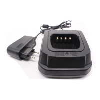
Chapter 15: TPA-CH-001 Single Battery Charger

Chapter 19: TOPA-SV-024 Test Unit

Related product manuals