90 General Information TP9100 Service Manual
© Tait Electronics Limited May 2005
Can Removal
and Installation
Cans are best removed and installed using a can-removal tool. If this tool is
available, technicians should refer to the documentation supplied with the
tool for the correct procedures. If the tool is not available, a hot-air tool may
be used instead. However, technicians require training in the best techniques
to employ in the absence of a can-removal tool. Such training is part of the
accreditation process for service centers.
Spare Cans It is good practice to discard any can that has been removed and replace it
with a spare can. If this is not done, special precautions are needed when re-
installing the original can. These precautions are discussed as part of the
training for accreditation.
4.7 SMT Repair Techniques
Standard
Procedures
Service centers carrying out level-2 repairs are expected to be familiar with
the standard techniques for the replacement of SMT components. However,
certain components on the main board require non-standard techniques and
these are discussed below. Another issue of concern is the procedure for
removing and installing cans. A discussion of the issue concludes this section.
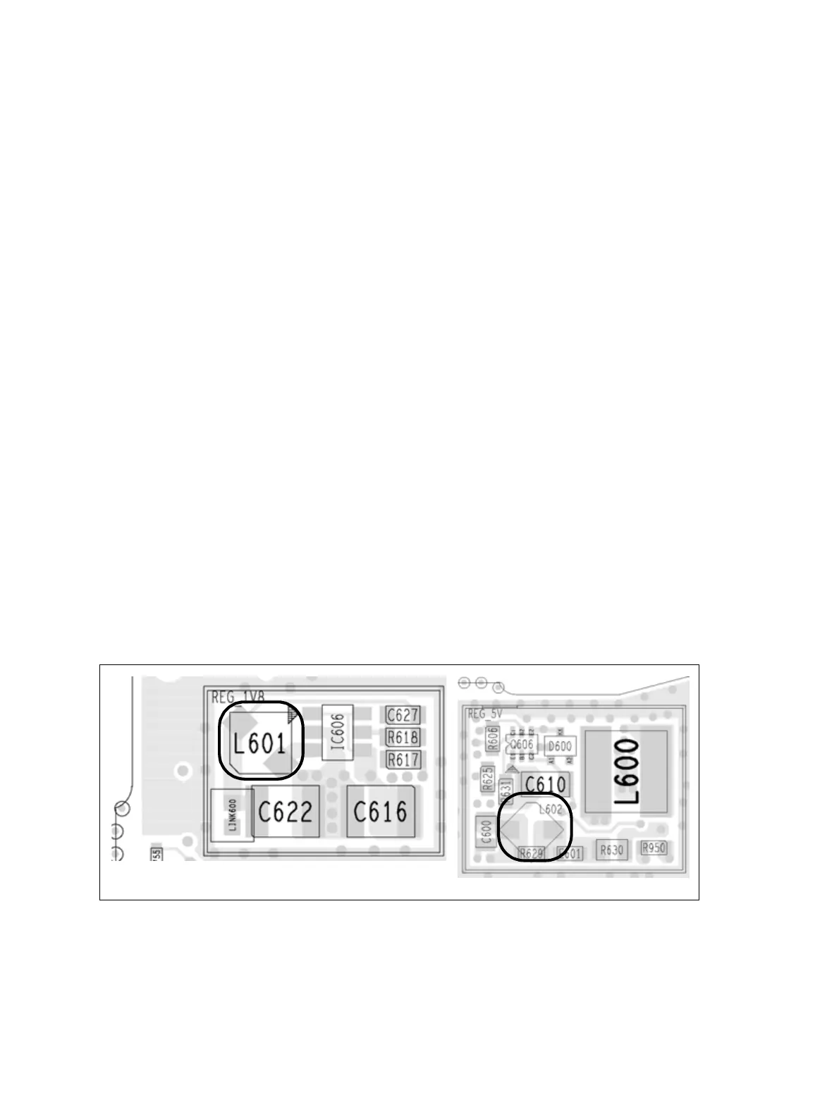
Non-standard
Procedures
Do not use the standard SMT repair techniques when replacing the
inductors L601 and L602. The standard techniques tend to produce
excessive heat, which will damage these components. Do not use a hot-air
tool or heat gun. Instead use solder paste and a standard soldering iron with
an iron tip with a specified temperature of 600°F (315°C). The inductors
are part of the SMPS of the power-supply circuitry on the bottom-side of
the board. Figure 4.4 on page 90 shows the locations of the components.
Figure 4.4 Locations of the inductors L601 and L602 (top side)
B1 board (H5 and H6 similar)
 Loading...


