128 Servicing Procedures TP9100 Service Manual
© Tait Electronics Limited May 2005
Task 2 —
Visual Inspection
Check the radio for mechanical loss or damage, even if the fault concerns a
function failure only. Inspect the radio as follows:
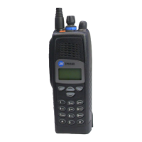
■ knob for power/volume control
■ knob for channel control, and 3-way actuator
■ antenna SMA connector
■ keys, lens and LCD
■ front panel
■ metal chassis
■ accessory connector
Important Engraving the chassis can significantly reduce the mechan-
ical strength and will void any warranty. If the chassis has
been engraved, it must be replaced.
Task 3 —
Power Up the Radio
With the radio connected to the test equipment as described in “Test
Equipment Setup” on page 86, attempt to power up the radio.
1. Apply power to the radio and turn on the power/volume control.
2. If the radio powers up successfully, go to Tas k 4
. If it does not, repair
the radio as described in “On/Off Switch Faulty” on page 141.
3. If the repair succeeded without the need for replacing the main board
go to Ta sk 4
. Otherwise continue with Step 4.
4. If the main board was replaced or if the repair failed, re-assemble the
radio as described in “Reassembling the Radio” on page 112.
Conclude with the tasks of “Final Tasks” on page 134.

 Loading...