118 Disassembly and Reassembly TP9100 Service Manual
© Tait Electronics Limited May 2005
Fitting the Non-SMT
Components
This section describes how to fit the following non-SMT components to
the main board:
■ power/volume potentiometer [RV1] B
■ 16-way/3-way selector switch [RSW1] C
■ antenna SMA connector [SK3] D
The circled numbers in this section refer to the items in Figure 5.13.
1. In case of the power/volume potentiometer
B, insert the potentio-
meter into the vector plate
E.
2. Tack-solder the component(s) to the main board at two diagonally
opposite legs.
3. Fit the main board to the chassis as described in “Fitting the
Main Board” on page 120, but do not fit the two knob nuts and the
SMA nut.
4. De-solder the legs tack-soldered in step 2.
5. Fit and tighten the two knob nuts and the SMA nut as described in
“Fitting the Main Board” on page 120.
6. Solder all legs of the component(s).
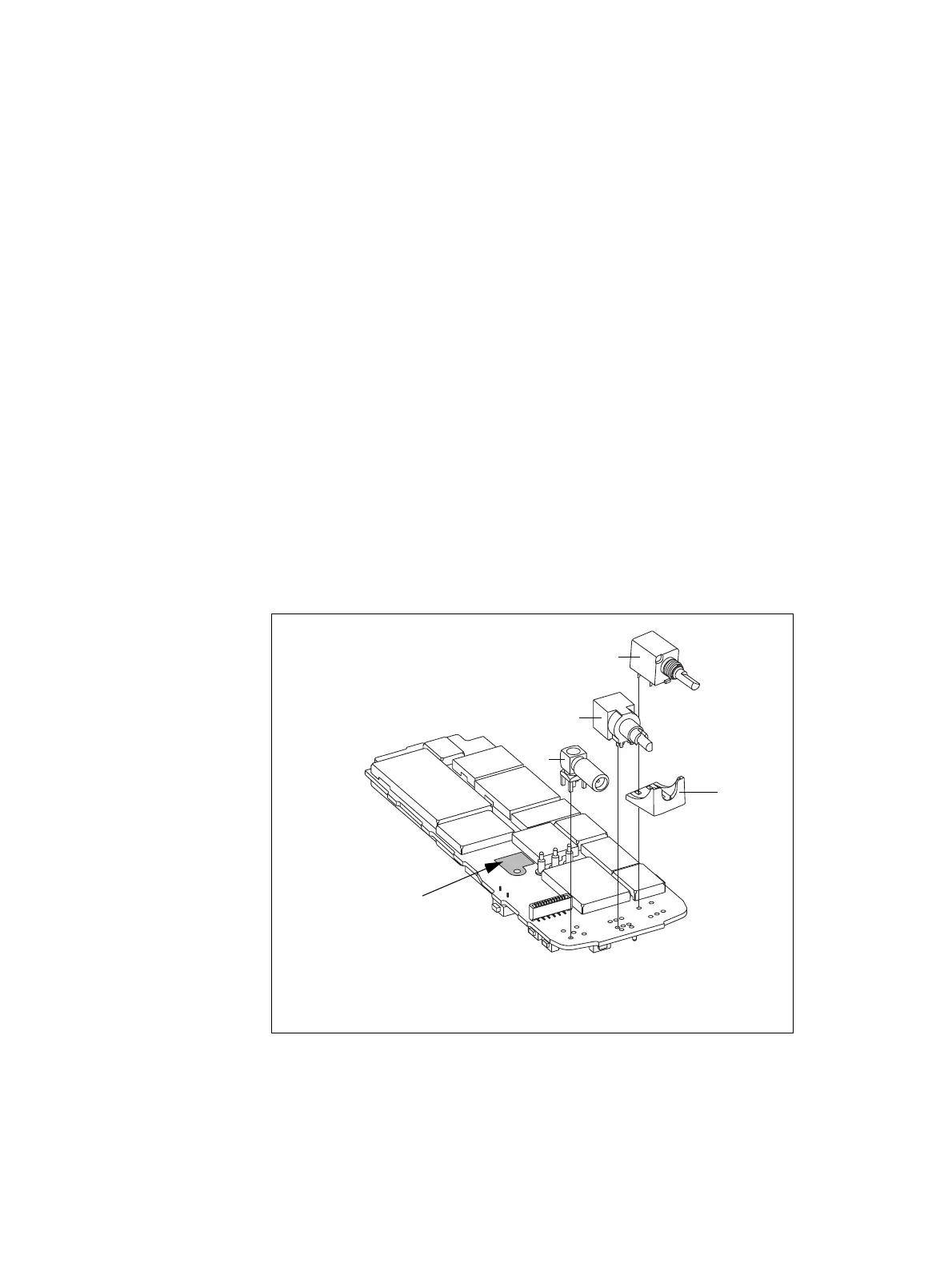
Figure 5.13 Fitting the non-SMT components
B
power/volume potentiometer
D
antenna SMA connector
C
16-way/3-way selector switch
E
vector plate
3658z_01
E
D
C
B
thermal paste
(PA)

 Loading...


