TP9100 Service Manual Description 29
© Tait Electronics Limited May 2005
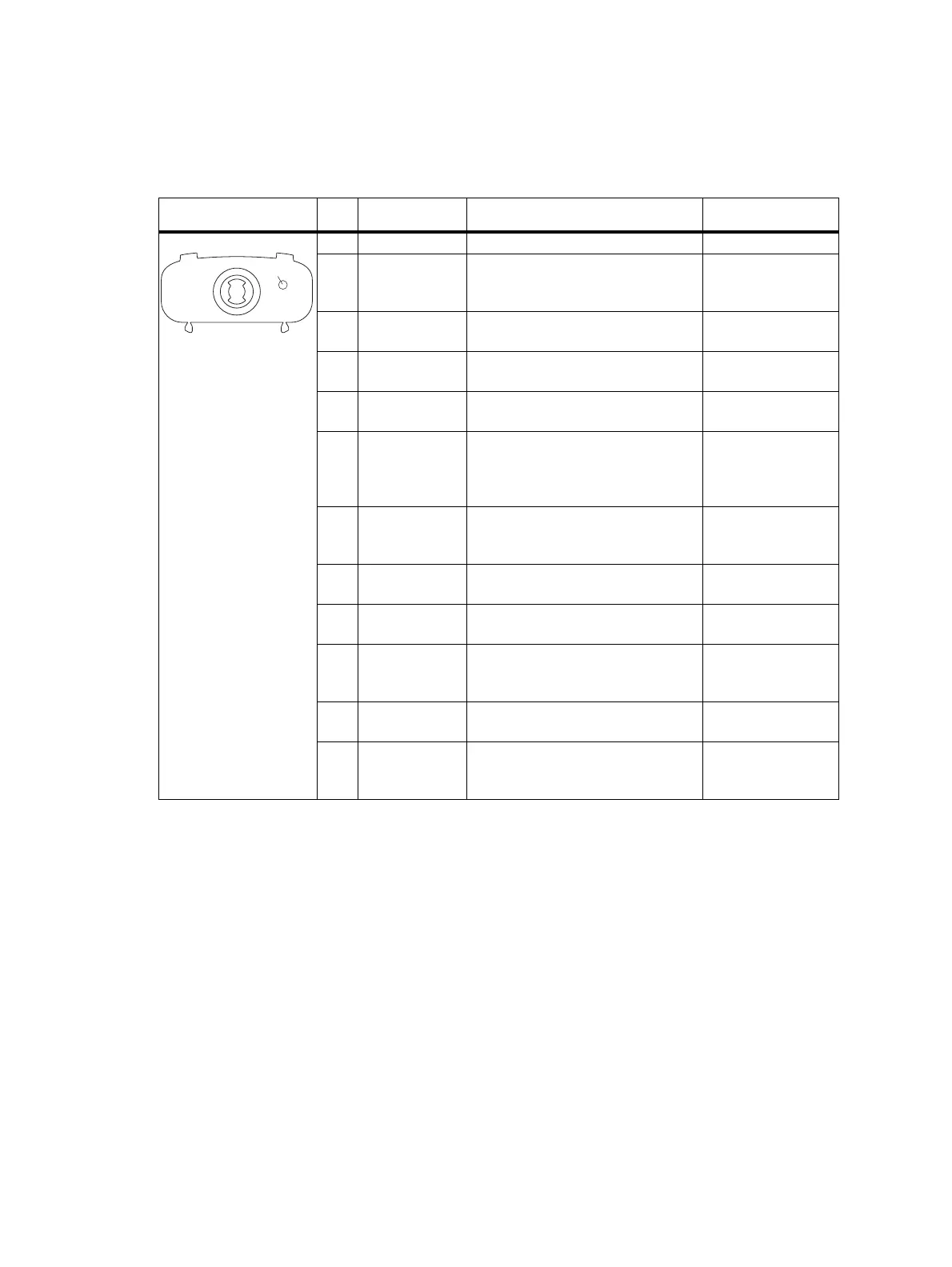
2.3.4 Accessory Connector
The 12 pins of the accessory connector and the chassis ground provide the
standard interface for external devices that are typically connected to a radio.
The two I/O lines are reserved for use by certain accessories, and cannot be
accessed in the programming application. Audio lines can be programmed
to tap into, or out of, different points in the audio processing chain. For
more information refer to the online help of the programming application.
Table 2.4 Accessory connector – pins and signals
Pinout Pin Signal name Description Signal type
1 AGND Analog ground Ground
2 ACC PWR Switched 3.3V supply. Supply is
switched off when radio is switched
off.
Power
3 ACC RXD Asynchronous serial port -
Receive data
Digital, 3V3 CMOS
4 AUD TAP OUT Programmable tap point out of the
Rx or Tx audio chain. DC-coupled.
Analog
5 ACC TXD Asynchronous serial port -
Transmit data
Digital, 3V3 CMOS
6 ACC MIC Accessory microphone input.
Electret microphone biasing
provided. Dynamic microphones are
not supported.
Analog
7 ACC GPIO2 Programmable function and
direction.
Digital, 3V3 CMOS
input; open collector
output with pullup
8 AUD TAP IN Programmable tap point into the Rx
or Tx audio chain. DC-coupled.
Analog
9 ACC–SPKR Accessory speaker output.
Balanced load configuration.
Analog
10 ACC GPIO1 Programmable function and
direction.
Digital, 3V3 CMOS
input; open collector
output with pullup
11 ACC+SPKR Accessory speaker output.
Balanced load configuration.
Analog
12 ACC PTT PTT input from accessory,
multiplexed with accessory function
key.
Analog
BCG
FDE
I1)1@
HJ1!
Chassis GND
rear view of radio
 Loading...


