43
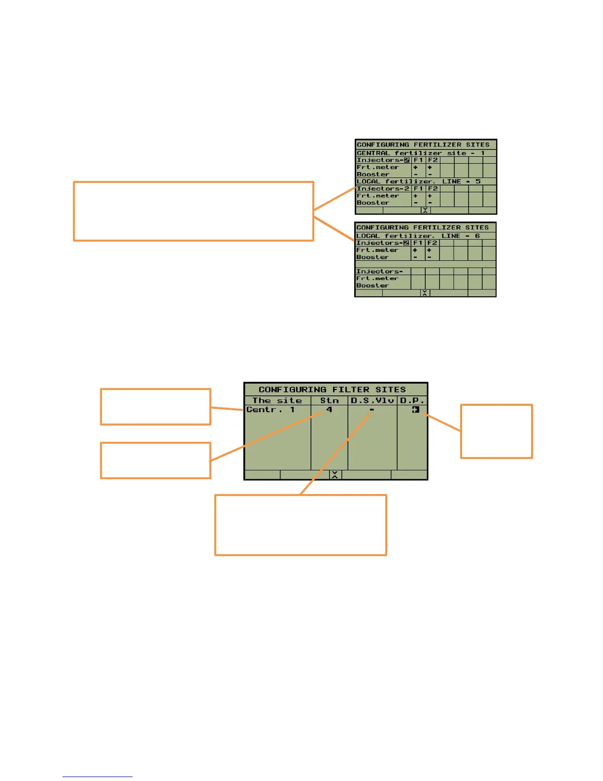
Next step is the definition of the fertilizer sites. For each site, the number of injectors has to be defined
and for each injector the existence of fertilizer meter and the existence of connection to a booster pump
need to be defined.
The next step will be the definition of the filters sites
At this stage we are finished with the network definition, pushing PAGE DOWN (), brings us
back to the top screen of NETWORK DEFINITION from where we can continue to the
HARDWARE DEFINITION by using the rightmost red function key, or pass again through the
NETWORK DEFINITION by using the PAGE DOWN key.
Central fert site No 1 and the local fert sites of line
5 and line 6 contain 2 injectors, each injector is
equipped with fert meter and uses no booster
pump.
There is one filter
site - Central No 1
There is a
pressure
differential
sensor
In this case, there is no Down
Stream Valve used. Generally
these valves are used for
increasing pressure while flushing.
The central filter site
has 4 stations