Tandy 1000
MC6845
REGISTER
FILE
DESCRIPTION
(See Table 2)
Technical Reference Manual
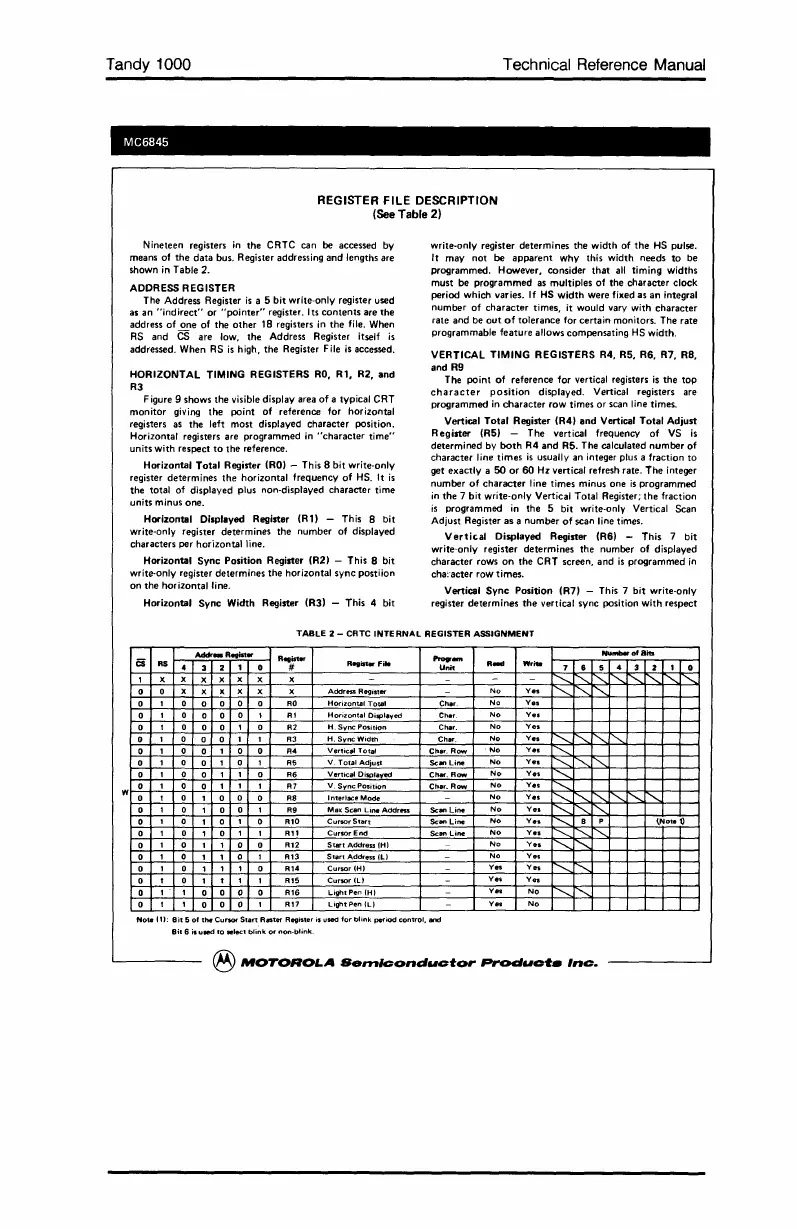
Nineteen registers
in
the CRTC can be accessed by
means of
the
data bus. Register addressing and lengths are
shown in Table 2.
ADDRESS REGISTER
The Address Register
is
a 5 bit write-only register used
as
an
"indirect"
or
"pointer"
register. Its
contents
are the
address
of
one
of
the
other
18 registers in
the
file. When
RS
and
CS
are low, the Address Register itself
is
addressed. When
RS
is
high, the Register File
is
accessed.
HORIZONTAL TIMING REGISTERS
RO,
RI.
R2, and
R3
Figure 9 shows the visible display area
of
a typical CRT
monitor giving the point
of
reference for horizontal
registers
as
the left most displayed character poSition.
Horizontal registers are programmed in
"character
time"
units with respect
to
the reference.
Horizontal Total Register
(RO)
- This 8 bit write-only
register determines the horizontal frequency
of
HS.
It
is
the total of displayed plus non-displayed character time
units minus one.
Horizontal Displayed Register
(RlI
- This 8 bit
write-only register determines the number of displayed
characters per horizontal line.
Horizontal Sync Position Register (R2) - This 8 bit
write·only register determines the horizontal sync postiion
on
the horizontal line.
Horizontal Sync Width Register (R3) - This 4 bit
write·only register determines the width of
the
HS
pulse.
It may
not
be
apparent
why
this width needs
to
be
programmed. However, consider
that
all
timing widths
must be programmed as multiples
of
the character clock
period which varies. If
HS
width
were fixed as an integral
number
of
character
times, it would vary with character
rate and be
out
of
tolerance for certain monitors. The rate
programmable feature allows compensating
HS
width,
VERTICAL TIMING REGISTERS R4, R5, R6, R7.
RB.
and R9
The point
of
reference for vertical registers
is
the
top
character
position
displayed. Vertical registers are
programmed
in
character
row times
or
scan line times.
Vertical
Total
Register (R4) and Vertical Total Adjust
Register
(R51
- The vertical frequency
of
VS
is
determined by
both
R4
and
R5. The calculated number
of
character line times
is
usually an integer plus a fraction
to
get exactly a
50
or
60
Hz
vertical refresh rate. The integer
number
of
character
line times minus one
is
programmed
in
the 7 bit write·only Vertical Total Register; the fraction
is
programmed in the 5 bit write·only Vertical Scan
Adjust Register as a number
of
scan line times.
Vertical
Displayed Register (R6) - This 7 bit
write'·only register determines the number
of
displayed
character rows
on
the CRT screen, and
is
programmed
in
cha:'acter row times.
Vertical
Sync
Position (R7) - This 7 bit write·only
register determines
the
vertical sync position with respect
w
TABLE 2 - CRTC INTERNAL REGISTER ASSIGNMENT
Addr_R
..
ist.
Register
"'--
Nulllberof8its
cs
RS
.
3
2
1
0 #
Regi:rt.fi
..
Unit
R_
Writll
7 6 5
4
3 2
1
0
I X
X
X
X
X
X X -
- -
-
...........
.........
"'-
.........
.........
1"'-
.........
"'-."
0
0
X
X X
X
X X
AddrHS
Register
-
No
Ve.
"'-."
"'-."
f".....
0
,
0
0 0
0
0
AO
Horizontal
Total
Char
No
Ve.
0
,
0
0 0
0
t
At
Horizontal
Displaved
Char
No
Ve.
0
t 0
0 0
I 0
Al
H.
Sync
Position
Char.
No
Ve.
0
,
0
0
0
, ,
A3
H.
Sync
Width
Char.
No
Ve.
...........
"'-."
1"-..1"-..
0
1 0
0
1 0 0
A4
VerticlJl
Total
Char.
Row
No
Ve.
'-....
0
1
0
0
I 0
I A5
V.
Total
Adjust
Scan
Line
No
Ve.
f"'-.....
1"-..1"-.-
0
,
0
0
I
,
0 A6
Venic.,IOisplaved
Ch
.....
Row
No
Ve.
.......
0
1
0
0
,
,
1
Al
V.
Sync
Position
Char.
Row
No
Ve.
.......
0
t 0
1 0
0
0
AS
Interlace
Mode
-
No
Ve.
'-....
1"'-."
["'-."
"'-." "'-."
"'-."
0
1 0
I 0
0
,
A9
Ma)(
Scan
Line
Address
Scan
Line
No
Ve.
"'-."
"'-.,,1"-..
0
,
0
,
0
,
0
A'O
Cursor
Start
Scan
Line
No
Ve.
.......
8
P
~Note
t)
0
I 0
1 0
I
,
AI'
Cursor
End
Scan
Line
No
Ve.
.......
.........
'"
0
,
0
,
I 0 0
A'l
Start
Address (HI
-
No
Ve.
'-.....
.........
0
1 0
1 1 0
I
AI3
Start
Address
(Ll
-
No
Ve.
0
1 0
1
1
,
0
AI.
Cursor
(HI -
Ve.
V
..
.......
.........
0
t 0
,
t 1
,
A,5
Cursor
ILl -
Yes
V
..
0
1 1
0
0 0 0
AI6
UghtPen
(HI -
Yes
No
......... .........
0
t 1
0
0
0
,
All
Light
Pen
(L)
-
Yes
No
Note
111:
Bit
5
of
the
Cursor
Start
R_fer
Register
is
used
for
blink
period
contrOl,
and
Bit
6
is
used
to
.Ieel
blink
or
non-blink
®
MOTOROLA
Senllconductor
Produc'f.
Inc.
 Loading...


