50
83532002 Rev C
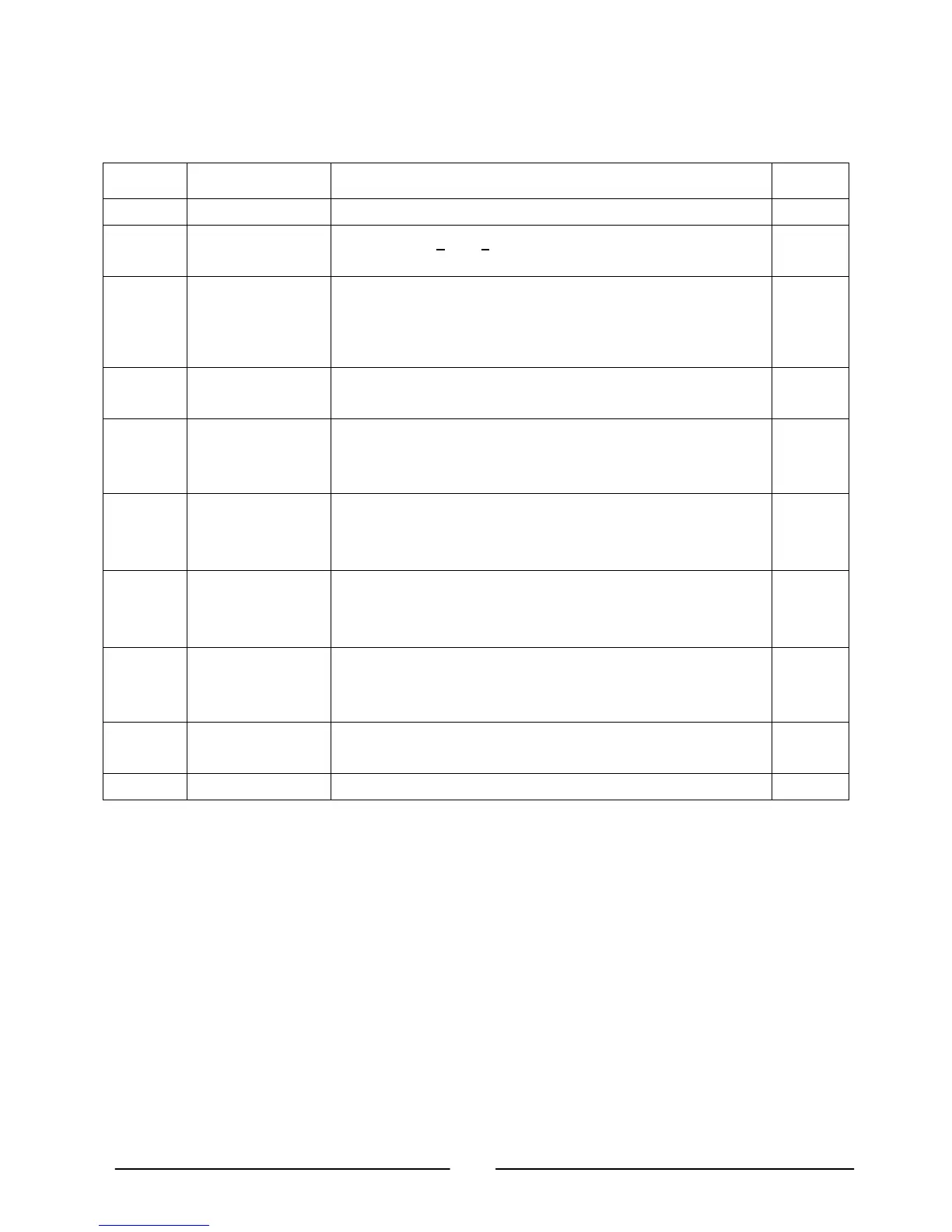
Table 4-2: Rear Panel Connections and Controls
Number Item Description
Section
1 AC input M6x10mm Stud terminal suitable for ring lugs. 3.7
2 DC output Bus-bars (7.5V < Vout < 300V models).
M6x10mm threaded-stud terminals (300V < Vout < 600V models).
3.9
3.9.1
3 Remote-In
connector
RJ-45 type connector, use for connecting power supplies to RS-232
or RS-485 port of computer for remote control purposes. When
using several power supplies in a power system, the first unit
Remote-In is connected to the computer and the remaining units are
daisy-chained, Remote-In to Remote-Out.
8.3
8.4
4 Remote Out
connector
RJ-45 type connector, used for daisy-chaining power supplies to
form a serial communication bus.
8.3
8.4
5 J1 Analog Remote
Program and
Monitor connector
Connector for remote analog interface. Includes Output voltage and
current programming and monitoring signals, Shut-off control
(electrical signal), Enable/Disable control (dry-contact), Power
Supply OK (PS_OK) signal and operation mode (CV/CC) signal.
4.5
4.4.1
6 SW1 Setup switch Nine position DIP-switch for selecting remote programming and
monitoring modes for Output Voltage, Current Limit and other
control functions.
4.4
4.4.1
4.4.2
7 J2 Remote sense
connector
Connector for making remote sensing connections to the load for
regulation of the load voltage and compensation of load wire drop.
3.8.2
3.10.2
3.10.3
8 Blank or Option
Plate
Blank sub-plate for standard units.
Other plates and connectors for options such as LAN, IEMD or
Isolated Analog. IEEE connector for units equipped with IEEE
programming option (shown).
Fig. 4-2
9 IEEE switch
LAN switch
Two position DIP-switch for selecting option mode or RS-232/RS-
485 mode. The options may be LAN or IEEE.
Fig. 4-2
10 Ground screw M5 x 20mm screw for Chassis ground connection. Fig. 4-2