8
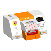
1. Emergency Stop
(cuts power to processor)
2. I/O Switch
(Switch to heater. Off--standby, Flash—warm up, Lit—temperature reach set value)
3. Cycle Start Push buttons
(Press and hold both buttons simultaneously 0.5s to start cycle process.
Interrupt Cycle----see section 3.5 item4, when switch ON this function, during cycle, press both start button again, would
interrupt the cycle. Heater would back to home position at once.)
4. Grippers
(hold cable splice in heating chamber)
5. Dual Release
(allow removal of splice by hand)
6. Calibration Socket
(Connect to the UHI temperature probe, to access auto-calibration process.)
7. Process button
(10 editable pre-set Single Process Selection Button. Can store 3 parameter, product size/process time/process
temperature)
8. Touch screen
(Display processor working information. Can edit processor parameter after login on.)
9. Heater Chamber
(heat shrinks product over splice)
10. Centering Mark
(Designed to centering tube visually)
11. Centering Plate
(See section 4.2.8 Auto Centering operation.)
12. Detection Plate
(See section 4.2.8 Auto Centering operation)
13. Offset knob
(Pull left knob and rotate, to adjust the 2X detection plates to left or right. Range: “+/-10mm”)
14. Distance knob
(Pull right knob and rotate, to adjust the distance between 2X detection plate. Range: “5~20mm”)