Scan
The measurement function Scan provides the scanning of individual control elements.
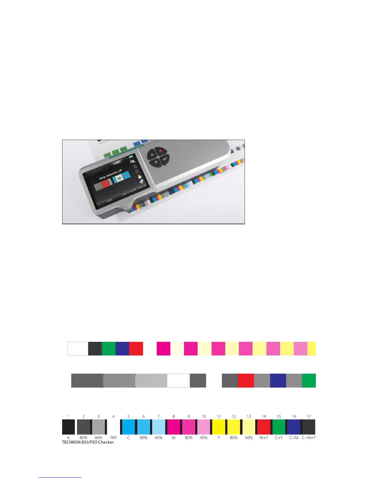
The scanning procedure is very easy. Choose the measurement function SCAN in the
device menu. Then place the measurement device on the print control strip. Take care
that the measurement aperture is positioned on the rst measurement patch (= start
position) and that the device edge is aligned to the print control strip (see picture).
Now press and hold the measurement button, move the device in constant speed
along the print control strip until you reach the last patch to be measured (= stop
position) and release the measurement button. If the measurement was carried out
successfully a short acoustic signal can be heard and all color patches are displayed in
the device. Using the SpectroConnect Export module measurement data can nally
be exported in any other Windows application e. g. Microsoft Excel™, Word™ or other
programs which can handle color data, e.g. a RIP calibration software.
Examples of control elements which can be scanned:
ECI Gray Control Strips: ECI/bvdm tvi 10 (i1) and M i1
TECHKON ISO/PSO Checker
ECI/bvdm
tvi 10 • v2
ECI/bvdm tvi 10 (i1) • 6 mm • Control strip with tone values in 10 percent steps for print process control in accordance with ISO 12647 • www.bvdm.org • www.eci.org
cmy 70 k 70 cmy 50 k 50 cmy 30 k 30 Stop cmy 70 Paper k 70 my cmy 50 cm k 50 cy cmy 30 cmy k 30 100 20 80 40 60 60 40 80 20 100 100 20 80 40 60 60 40 80 20 100 < Start
ECI/bvdm Gray Control Strip (M i1) • FOGRA30 • ISO 12647-2 gray balance condition ‘CIELAB black ink’ • O set on uncoated yellowish paper (PT 5) • ISO 12647-2:2004/Amd 1 • Reference FOGRA30.txt (www.fogra.org) • www.eci.org, www.bvdm.org