7 LIST OF FIGURES
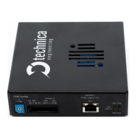
Figure 1-1: Capture_Module_Eth_Combo ......................................................................... 5
Figure 2-1: Label of CM_Eth_Combo with pinning information .................................... 10
Figure 2-2: Power Connector ........................................................................................... 11
Figure 2-3: MQS Connectors backside ............................................................................ 12
Figure 2-4: MATEnet Connectors backside .................................................................... 13
Figure 2-5: LED allotment on front of the device ............................................................ 15
Figure 3-1: Home Screen CM_Eth_Combo ...................................................................... 17
Figure 4-1: Save Configuration ........................................................................................ 18
Figure 4-2: CM_Eth_Combo Home Screen...................................................................... 18
Figure 4-3: System Information tab ................................................................................. 19
Figure 4-4: IP-addresses ................................................................................................... 20
Figure 4-5: Control Panel .................................................................................................. 21
Figure 4-6: Restart device ................................................................................................. 22
Figure 4-7: handling of configuration files ...................................................................... 22
Figure 4-8: Prevent standby ............................................................................................. 24
Figure 4-9: WakeUp lines .................................................................................................. 25
Figure 4-10: WUP time to LOW ........................................................................................ 26
Figure 4-11: Sleep Timeout .............................................................................................. 26
Figure 4-12: Date and Time .............................................................................................. 27
Figure 4-13: Switch Status tab ......................................................................................... 28
Figure 4-14: Spy multiplexer Overview (no Filters set) .................................................. 29
Figure 4-15: Overview Filters Table ................................................................................. 32
Figure 4-16: Filters Table .................................................................................................. 33
Figure 4-17: User interface basic filter (Add new entry) ................................................ 34
Figure 4-18: User interface advanced filter ..................................................................... 35
Figure 4-19: Host Port ...................................................................................................... 37
Figure 4-20: GB port .......................................................................................................... 38
Figure 4-21: 100BASE-T1Port .......................................................................................... 40
Figure 4-22: 1000BASE-T1 Ports ..................................................................................... 42
Figure 4-23: 802.1AS PTP bridge .................................................................................... 44
Figure 4-24: P-Delay .......................................................................................................... 45
Figure 4-25: Example Advance Filter Drop ...................................................................... 46
Figure 4-26: Example test setup for inject ...................................................................... 47
Figure 4-27: Example for IP Injection .............................................................................. 48
Figure 4-28: Example for IP Injection .............................................................................. 48
Figure 4-29: Example for IP Injection .............................................................................. 48
Figure 5-1: Schematic with MediaConverter .................................................................. 50
Figure 5-2: Schematic with MediaGateway .................................................................... 51
Figure 5-3: Example of MediaGateway and Capture Module (CM_ETH_Combo)
assembly ........................................................................................................................... 51
Figure 5-4:Power and BroadR-Reach Connector for Capture Module .......................... 52
Figure 5-5: MediaGateway connection in detail ............................................................. 52