AccuLoad IV Installation & Maintenance Manual
Installation 31
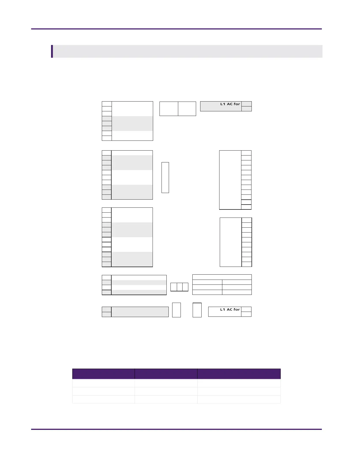
The following drawing shows the A4I board’s I/O connections.
The A4I board has jumpers that allow customization. If the A4I board is connected to additive meters for
which the transmitters require DC power, the voltage select jumpers (see Table 14: A4I Jumper Settings)
are used to set the meter power supply voltage to 5, 12, or 24 VDC.
Firmware updates are not available over serial connections in the A4I.
Table 14: A4I Jumper Settings
Designation Jumpers Description
5V 1 and 2 24 V – +V Out
12V 3 and 4 12 V – +V Out
24V 5 and 6 5 V – +V Out
Figure 19: A4I Connections
Enet
2
Enet
1
S1
OFF
1
8
ON
TB9
Out 1-Out 10
TB8
N/C 12
N/C 11
Out 1 10
Out 2 9
Out 3 8
Out 4 7
Out 5 6
Out 6 5
Out 7 4
Out 8 3
Out 9 2
Out 10 1
CN5
531
•
•
•
•
•
•
642
F1
TB5
1 +V Out
2 Inj Pulse/DC In 1
3 Common
4 +V Out
5 Inj Pulse/DC In 2
6 Common
7 +V Out
8 Inj Pulse/DC In 3
TB4
1 Common
2 +V Out
3 Inj Pulse/DC In 4
4 Common
5 +V Out
6 Inj Pulse/DC In 5
7 Common
8 +V Out
9 Inj Pulse/DC In 6
10 Common
TB3
1 +V Out
2 Inj Pulse/DC In 7
3 Common
4 +V Out
5 Inj Pulse/DC In 8
6 Common
7 +V Out
8 Inj Pulse/DC In 9
9 Common
10 +V Out
11 Inj Pulse/DC In 10
12 Common
TB2
1 RS485 (Rx -)
2 RS485 (Rx +)/RS232 (Rx)
3 RS485 (Tx -)
4 RS485 (Tx +)/RS232 (Tx)
TB1
1 +24 VDC
DC Input
2 Gnd/RS232 Com
TB7
Out 11 10
Out 12 9
Out 13 8
Out 14 7
Out 15 6
Out 16 5
Out 17 4
Out 18 3
Out 19 2
Out 20 1
TB6
Out 11-Out 20
Earth Ground
to Circuit Ground
Injector +V Out Selection
1-2 24V
3-4 12V
5-6 5V
J1
•
•
A4I