Adjustments—455/A2/B2
d. Set VERT MODE to CH 2.
e. Move 20 mV amplitude-calibrator signal to CH 2
input connector.
b. Set: CH 2 VOLTS/DIV 5 mV
ATIM E/DIV .05 jus
ASLOPE OUT: +
f. ADJUST-CH 2 Gain R4273 for exactly 4 divisions
of display.
g. Disconnect test setup.
B4. LOW-FREQUENCY INPUT COMPENSATIONS
a. Connect 1 kHz square-wave-generator signal from
high amplitude output to CH 1 input connector via
50 £2 cable, 10X attenuator, 50 £2 termination, and
20 pF input RC Normalizer.
b. Set generator output for 6 division display. Main
tain 6 division display throughout this step, adding or
removing attenuators as required.
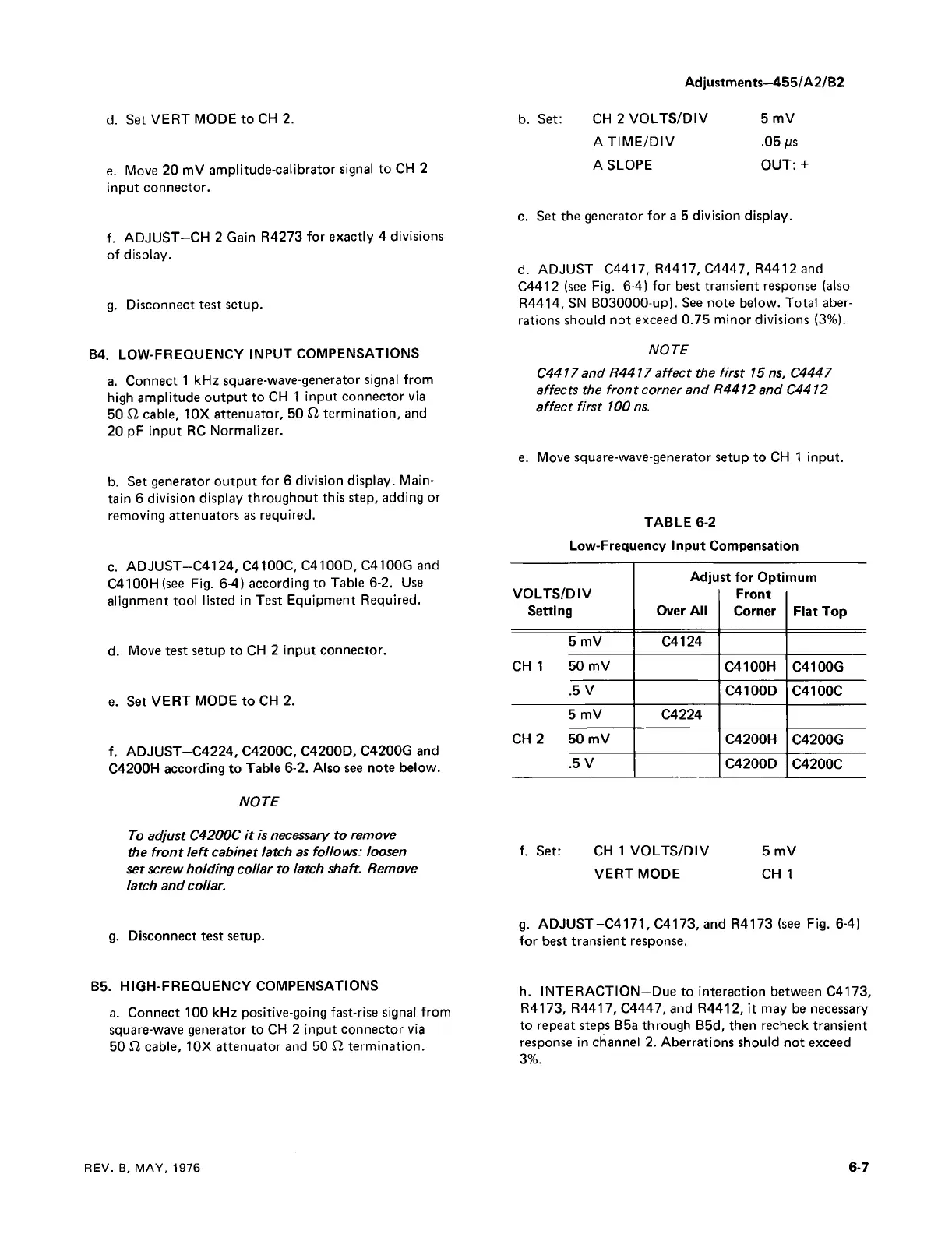
c. ADJUST—C4124, C4100C, C4100D, C4100G and
C4100H(see Fig. 6-4) according to Table 6-2. Use
alignment tool listed in Test Equipment Required.
d. Move test setup to CH 2 input connector.
e. Set VERT MODE to CH 2.
f. ADJUST—C4224, C4200C, C4200D, C4200G and
C4200H according to Table 6-2. Also see note below.
NOTE
To adjust C4200C it is necessary to remove
the front left cabinet latch as follows: loosen
set screw holding collar to latch shaft. Remove
latch and collar.
g. Disconnect test setup.
B5. HIGH-FREQUENCY COMPENSATIONS
a. Connect 100 kHz positive-going fast-rise signal from
square-wave generator to CH 2 input connector via
50 £2 cable, 10X attenuator and 50 £2 termination.
c. Set the generator for a 5 division display.
d. ADJUST—C4417, R4417, C4447, R4412 and
C4412 (see Fig. 6-4) for best transient response (also
R4414, SN B030000-up). See note below. Total aber
rations should not exceed 0.75 minor divisions (3%).
NOTE
C4417 and R4417 affect the first 15 ns, C4447
affects the front corner and R4412 and C4412
affect first 100 ns.
e. Move square-wave-generator setup to CH 1 input.
TABLE 6-2
Low-Frequency Input Compensation
VOLTS/DIV
Setting
Adju
Over All
st for Opti
Front
Corner
mum
Flat Top
5 mV C4124
CH 1 50 mV
C4100H
C4100G
.5 V C4100D
C4100C
5 mV C4224
CH 2 50 mV
C4200H
C4200G
.5 V
C4200D
C4200C
f. Set: CH 1 VOLTS/DIV 5 mV
VERT MODE C H I
g. ADJUST—C4171, C4173, and R4173 (see Fig. 6-4)
for best transient response.
h. INTERACTION—Due to interaction between C4173,
R4173, R4417, C4447, and R4412, it may be necessary
to repeat steps B5a through B5d, then recheck transient
response in channel 2. Aberrations should not exceed
3%.
REV. B, MAY, 1976 6-7