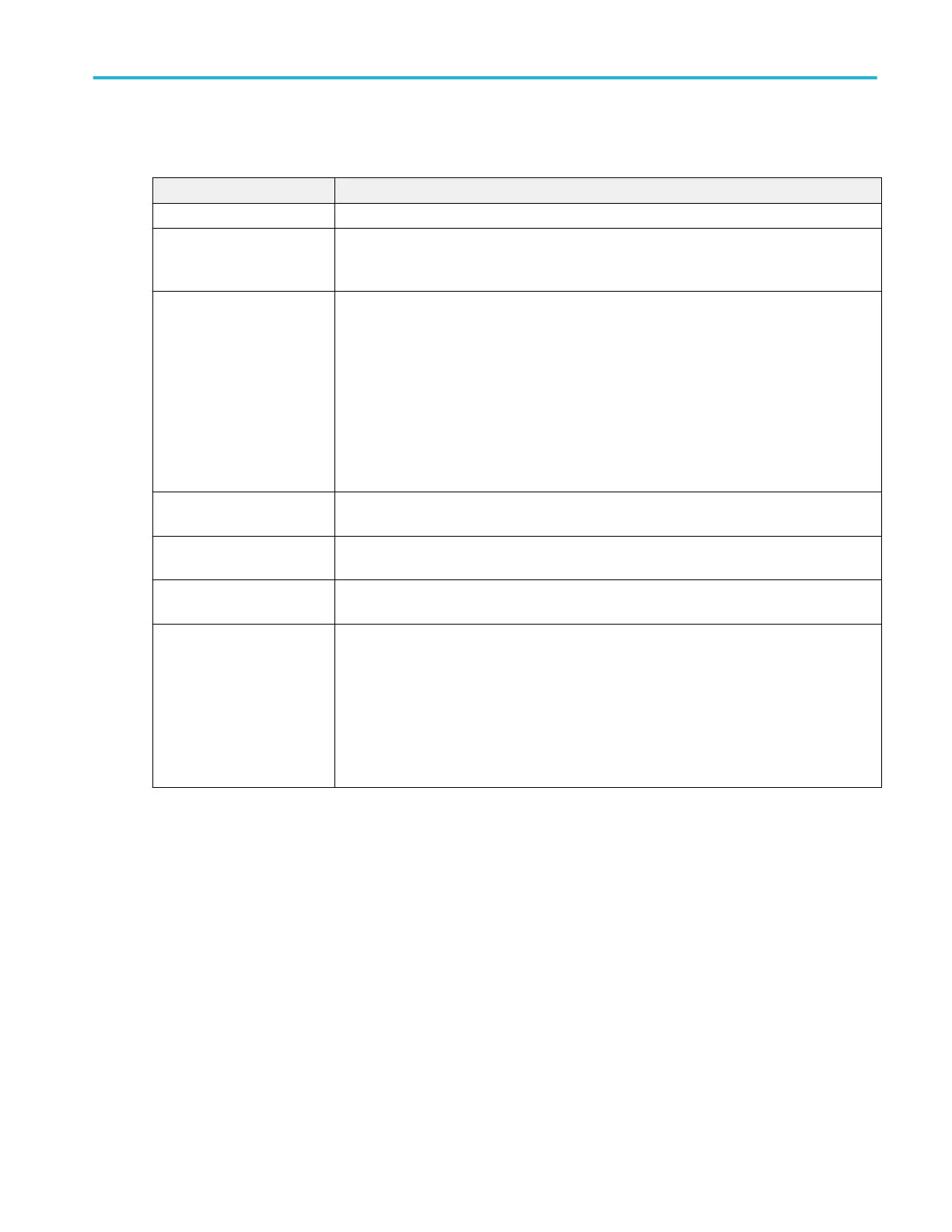
Settings panel (Logic Trigger configuration menu) - fields and controls.
Field or control Description
Use Clock Edge? Enables or disables finding logic patterns that occur on the specified clock edge.
Logic Pattern Define Inputs Opens the Logic Trigger - Define Inputs menu where you define the logic state (High, Low, or
Don't Care), and the signal threshold level that defines the logic state (high or low), for each
analog or digital signal. See Logic Trigger - Define Inputs configuration menu on page 383.
Trigger When
(Use Clock Edge = No)
Defines the waveform condition on which to trigger.
■
Goes True: All conditions change to a true state.
■
Goes False: All conditions change to a false state.
■
Is True > Limit: Condition remains true longer than a specified time.
■
Is True < Limit: Condition remains true for less than a specified time.
■
Is True = Limit: Condition remains true for a specified time (within ± 5%).
■
Is True ≠ Limit: Condition does not remain true for a specified time (within ± 5%).
Clock Source
(Use Clock Edge = Yes)
Sets the signal to use as the clock. The clock signal can be a digital, analog, or math waveform
Clock Edge
(Use Clock Edge = Yes)
Sets the signal transition edge (rising, falling, or either) for evaluating the logic condition at that
clock transition.
Clock Threshold
(Use Clock Edge = Yes)
Sets the threshold level that the clock signal must pass through to be considered a valid
transition. The clock threshold value is independent of the input signal threshold(s).
Define Logic Sets the logic condition that must occur with all inputs to cause a trigger event.
Sets the logic condition that must occur with all inputs.
■
AND: All conditions are true.
■
OR: Any condition is true.
■
NAND: One or more conditions are true.
■
NOR: No conditions are true.
Menus and dialog boxes
MSO54, MSO56, MSO58, MSO58LP, MSO64 Help 381
 Loading...


