When in Zoom mode, the Waveform Record View is replaced with the Zoom Overview. See The Zoom user interface
elements on page 60.
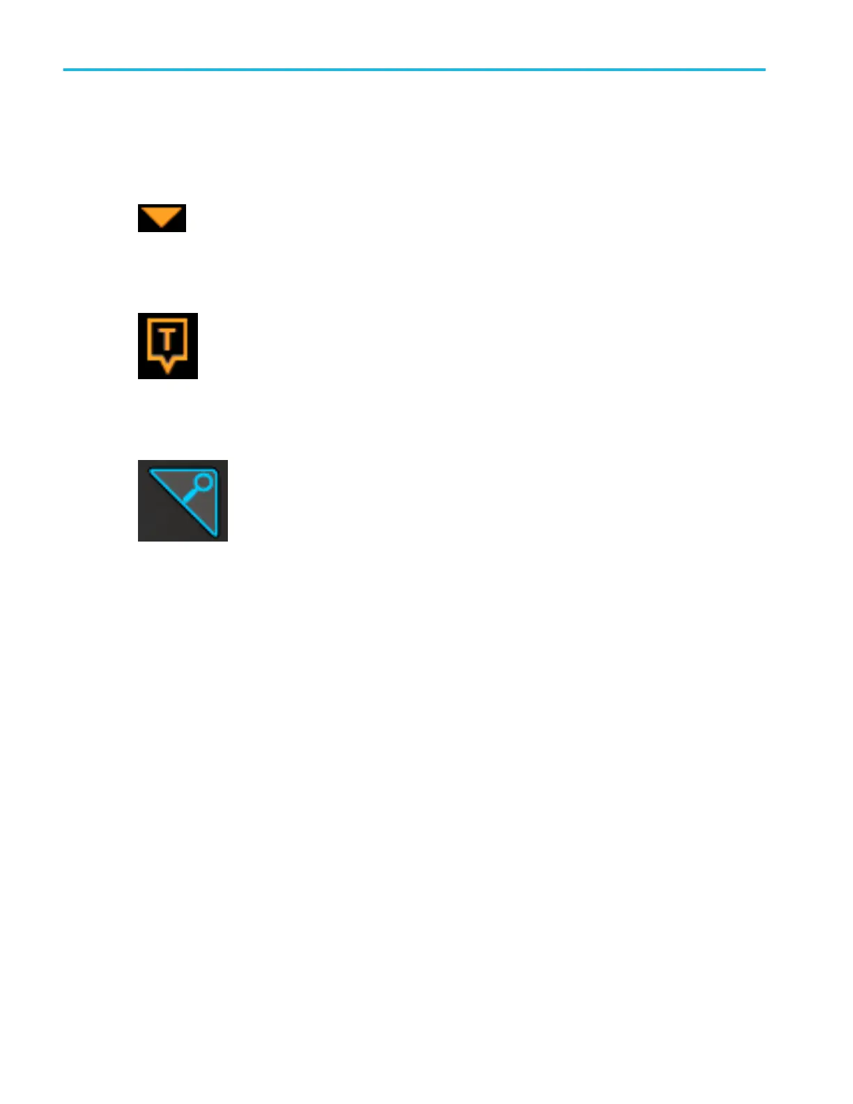
2. The Expansion Point icon on the waveform view shows the center point around which the waveform expands and
compresses when changing horizontal settings.
3. The Trigger Position Indicator shows where the trigger event occurred in the waveform record. The trigger icon is displayed
in the waveform slice that is the trigger source.
4. The Zoom icon (in upper right corner of Waveform and Plot views) toggles zoom on and off. The front panel Zoom button
and knobs also turn on zoom mode and change the position and horizontal size of the Zoom Box.
5. The Trigger Level Indicator icon(s) shows the trigger level on the trigger source waveform. Some trigger types require two
trigger levels.
6. Measurement and Search badges show measurement and search results. See Badges on page 52. See Add a
measurement on page 94.
7. The Results Bar Handle opens or closes the Results bar, to maximize waveform screen viewing when needed. To reopen
the Results bar, either tap the handle icon or swipe left from the right side of the display.
8. The System badges show global instrument settings (Horizontal, Trigger, Acquisition, Run/Stop status, and Date/Time).
See Badges on page 52.
9. The Inactive Channel buttons add channel waveforms to the Waveform view and add an associated Channel badge to the
Settings bar.
The Add New Math, Add New Ref, and Add New Bus buttons add the corresponding signal to the Waveform view, and
add an associated Waveform badge to the Settings bar. You can add any number of Math, Reference, and Bus waveforms,
limited only by system memory.
The optional AFG button opens the AFG configuration menu to set and enable the AFG output. This button is only present if
the AFG option is installed.
The optional DVM button lets you use an analog probe to take DC, AC RMS, or DC+AC RMS voltage measurements on
your DUT. Tap the button to add a DVM badge to the Results Bar and open a configuration menu. The DVM option also
enables a trigger frequency counter, accessible from the Mode & Holdoff panel in the Trigger badge menu. This button is
only present if the DVM option is installed.
10. Double-tap a badge to open its associated configuration menu. See Badges on page 52. See Configuration menus on
page 59.
If you add more Channel or Waveform badges than can fit in the waveform badge display area, tap the scroll buttons at
each end of the waveform badge area to scroll and display hidden badges.
Getting acquainted with your instrument
50 MSO54, MSO56, MSO58, MSO58LP, MSO64 Help
 Loading...


