Operating Information
2-- 2
TPS2000 Series Digital Storage Oscilloscopes Service Manual
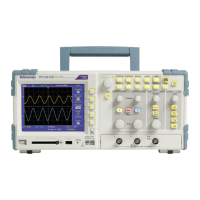
H Autoranging for quick set up and hands-free operation
H Probe Check Wizard
H Cursors with readouts
H Trigger frequency readout
H Eleven automatic measurements
H Waveform averaging and peak detection
H Dual time base
H Math functions: +, --, and × operations
H Math Fast Fourier Transform (FFT)
H Pulse Width trigger capability
H Video trigger capability with line-selectable triggering
H External trigger
H Setup and waveform storage
H Removable mass storage
H Variable persistence display
H RS-232 and Centronics ports
H OpenChoice PC Communications software
H User interface in ten user-selectable languages
Attach Reference Leads Correctly
NOTE. You must attach the probe reference lead for each channel directly to your
circuit. These attachments are required because the oscilloscope channels are
electrically isolated; they do not share a common connection. Use the shortest
possible reference lead with each probe to maintain good signal fidelity.
The probe reference lead presents a higher capacitive load to the circuit under
test than the probe tip. When taking a floating measurement between two nodes
of a circuit, attach the probe reference lead to the lowest impedance or least
dynamic of the two nodes.

 Loading...


