Performance Verification
TPS2000 Series Digital Storage Oscilloscopes S ervice Manual
4-7
10. Check that the rising edge of the marker crosses the center horizontal
graticule line within ±2 divisions of center graticule.
NOTE. One division of displacement from graticule center corresponds to
a 25 ppm time base error.
11. Disconnect the test setup.
This test checks the edge trigger sensitivity for all input channels.
1. Set up the oscilloscope using the following steps:
Press menu button Select menu option Select setting
DEFAULT SETUP — —
CH 1 (or whatever channel is
currently being tested).
Voltage Probe 1X
TRIGGER Mode Normal
ACQUIRE Sample —
MEASURE
Source An unchecked channel
Type Pk-Pk
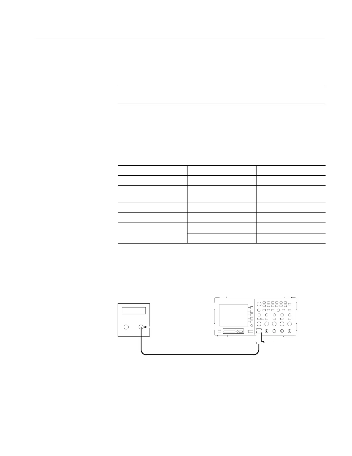
2. As shown below, connect the oscilloscope channel selected in the table to the
leveled sine wave generator.
Digitizing oscilloscope
Leveled
sine wave
generator
50 Ω feedthrough
terminator
BNC cable
Output
3. Set the oscilloscope VOLTS/DIV to 500 mV/div.
4. Set the oscilloscope SEC/DIV to 25 ns/div.
Check Edge Trigger
Sensitivity
 Loading...
