TPS2000 Series Digital Storage Oscilloscopes Service Manual
3-- 1
Theory of Operation
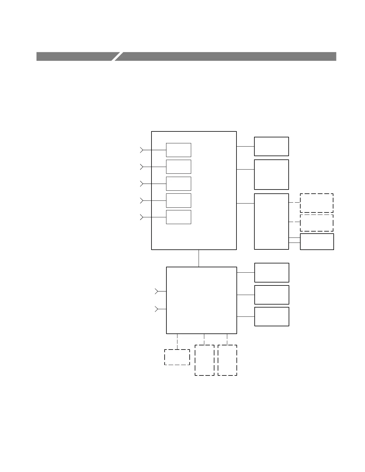
This section describes the electrical operation of the TPS2000 Series oscilloscope
to the module level. It describes the basic operation of each functional circuit
block shown in Figure 3--1.
Acquisition Board
J201
CH1
CH2
CH3
CH4
EXT
Trig
LCD
Display
J202
Front
Panel
J2100
J1
J302
Compact
FLASH Card
Application
Key
Probe Comp
Output
Compact
Flash Board
J1
J3
IO Board
J650
Fan
J600
LCD
Backlight
J640
ON/OFF
Switch
Battery
1
J1
Battery
2
J2
Parallel
Port
J620
J100
J610
DC Input
RS-232
J630
J3
J300
J500
J1000
J1200
J1700
Isolation
Circuit
Isolation
Circuit
Isolation
Circuit
Isolation
Circuit
Isolation
Circuit
Figure 3--1: TPS2000 Series module-level block diagram, remove CH3 and CH4 for a 2-channel version
 Loading...
