Maintenance
6-- 6
TPS2000 Series Digital Storage Oscilloscopes Service Manual
To remove and replace the fan, backlight inverter board, or IO board, refer to
Table 6--2.
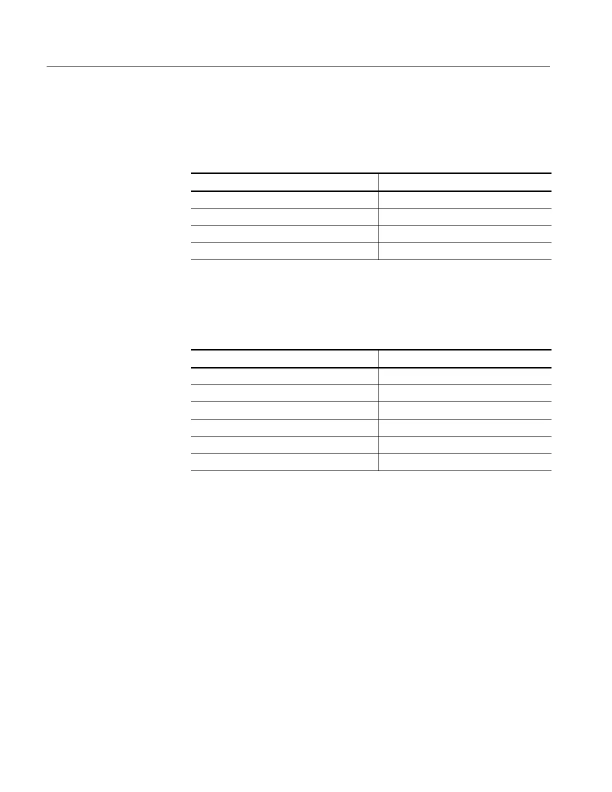
Table 6--2: Procedures for module replacement by removing the rear case
Remove module See procedure on
Rear case (Remove for following procedures.) Page 6--7
Fan Page 6--9
Backlight inverter board Page 6--9. Remove fan first.
IO board Page 6--10
To remove and replace the acquisition board, front panel board, LCD display,
compact flash module, or keypad, refer to Table 6--3.
Table 6--3: Procedures for module replacement by removing the front case
Remove module See procedure on
Front case (Remove for following procedures.) Page 6--11
Acquisition board Page 6--14. Remove IO board first.
Front panel board Page 6--16
Display module Page 6--17. Remove front panel board first.
Compact flash module Page 6--18. Remove acquisition board first.
Keypad Page 6--18
Use the following tools to remove and replace modules in the oscilloscope:
H Torque-limiting screwdriver, long shank, 8 in-lb (.85 N
⋅m) range with Torx®
T-15 tip
H 16 mm (5/8 inch) deep socket with wide center hole (S
⋅K Hand Tool Corp.,
S-K #40818, or equivalent)
H Torque wrench to 40 in-lb (4.5 N
⋅m)
H Screwdriver with 1/4 inch (6.35 mm) flat blade
H Pliers (all-purpose and needle-nose)
Tools Required
 Loading...
