Maintenance
TPS2000 Series Digital Storage Oscilloscopes Service Manual
6-- 25
When the oscilloscope is on and operating properly, the PROBE COMP output
should generate a square wave, approximately 5 V in amplitude, at a 1 kHz
frequency. Use the oscilloscope and set the Attenuation switch to 10X on the
P2100 probe to probe this output.
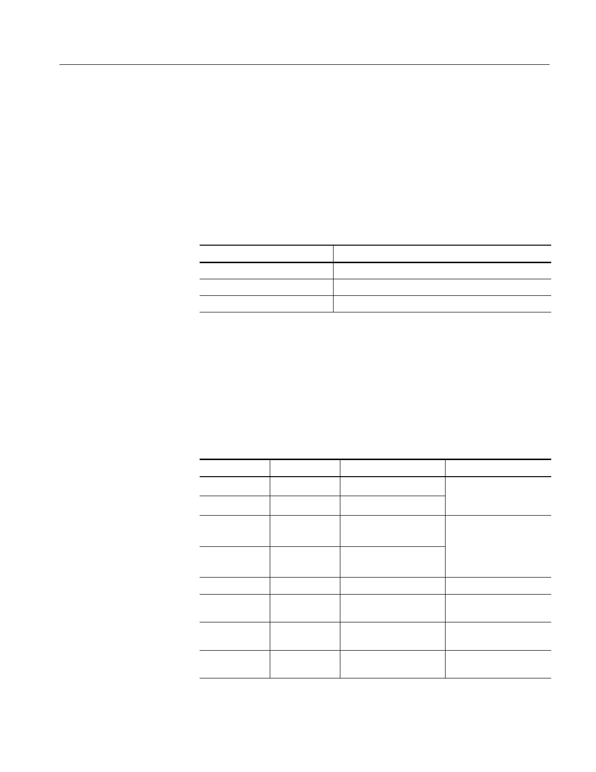
As shown in the table below, there are two cases of defects. Either the 1 kHz
signal is on and the IO and Acquisition boards are both active and functionally
capable of performing an acquisition, or one of those two modules is not
performing correctly. While a large number of different possible frequencies
exist, all involve detected failures on the Acquisition or IO boards due to failure.
Signal at PROBE COMP Possible problem
1 kHz signal, no display Troubleshoot the display
Non-1 kHz signal Troubleshoot the Acquisition board
No signal Troubleshoot the power supply
Failures that occur during the power-up diagnostics or normal oscilloscope
operation place an entry in the error log.
Accessing the error log. The error log list can be accessed anytime by pushing the
UTILITY button and then selecting Options > Error Log. Table 6--4 lists the
error codes and probable causes.
Table 6--4: List of error codes
Number ID Description Probable cause
0 Battery Battery 1 alarm Battery hardware failure;
1 Battery Battery 2 alarm
rep
ace
a
er
.
errors
persists, contact Tektronix
2 Battery PIC Communication May occur sporadically
during normal operation. If
3 Battery PIC HW Failure
errors occur repea
e
,a
hardware failure may exist.
Contact Tektronix.
0 Diagnostics Diagnostics internal error Contact Tektronix
4 Diagnostics CH1 diagnostics failed Acquisition board or power
supply failure
5 Diagnostics CH2 diagnostics failed Acquisition board or power
supply failure
7 Diagnostics ADG421 diagnostics failed Acquisition board or power
supply failure
PROBE COMP Output
Using the Error Log
 Loading...
