Performance Verification
TPS2000 Series Digital Storage Oscilloscopes S ervice Manual
4-5
This test checks the bandwidth of all input channels.
1. Set up the oscilloscope using the following steps:
Press menu button Select menu option Select setting
DEFAULT SETUP — —
CH 1 (or whatever channel i s
currently being tested).
Voltage Probe 1X
ACQUIRE Average 16
TRIGGER Coupling Noise
MEASURE
Source An unchecked channel
Type Pk-Pk
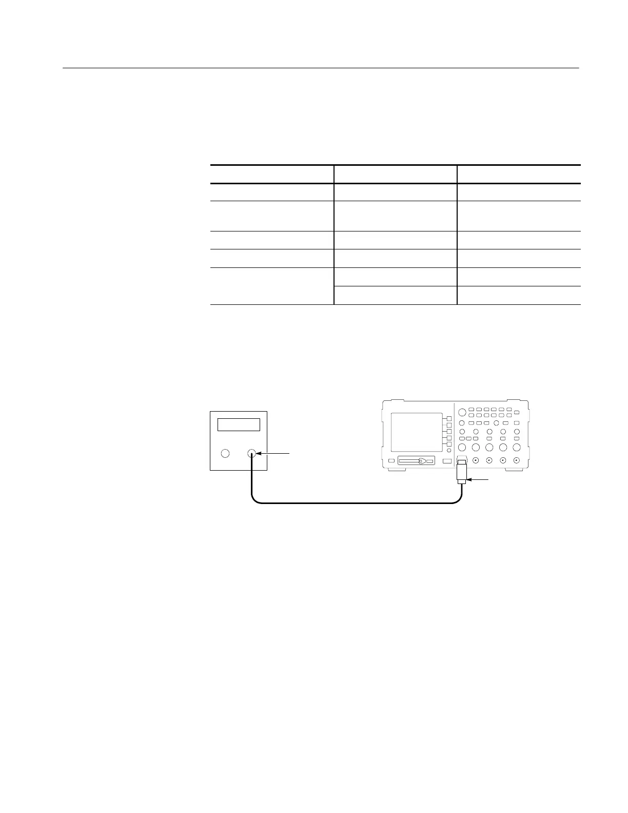
2. As shown below, connect the oscilloscope channel selected in the table to the
leveled sine wave generator.
Digitizing oscilloscope
Leveled
sine wave
generator
50 Ω feedthrough
terminator
BNC cable
Output
3. Set the oscilloscope VOLTS/DIV to 500 mV/div.
4. Set the oscilloscope SEC/DIV to 10 s/div.
5. Set the leveled sine wave generator frequency to 50 kHz.
6. Set the leveled sine wave generator output level so the peak-to-peak
measurement is between 2.98 V and 3.02 V.
7. Set the leveled sine wave generator frequency to:
H 100 MHz if you are checking a TPS2012/2014
H 200 MHz if you are checking a TPS2024.
8. Set the oscilloscope SEC/DIV to 10 ns/div.
9. Check that the peak-to-peak measurement is ≥2.12 V.
Check Bandwidth
 Loading...
