LE910Cx Hardware Design Guide
1VV0301298 Rev.40 Page 69 of 149 2023-03-16
Not Subject to NDA
8. HARDWARE INTERFACES
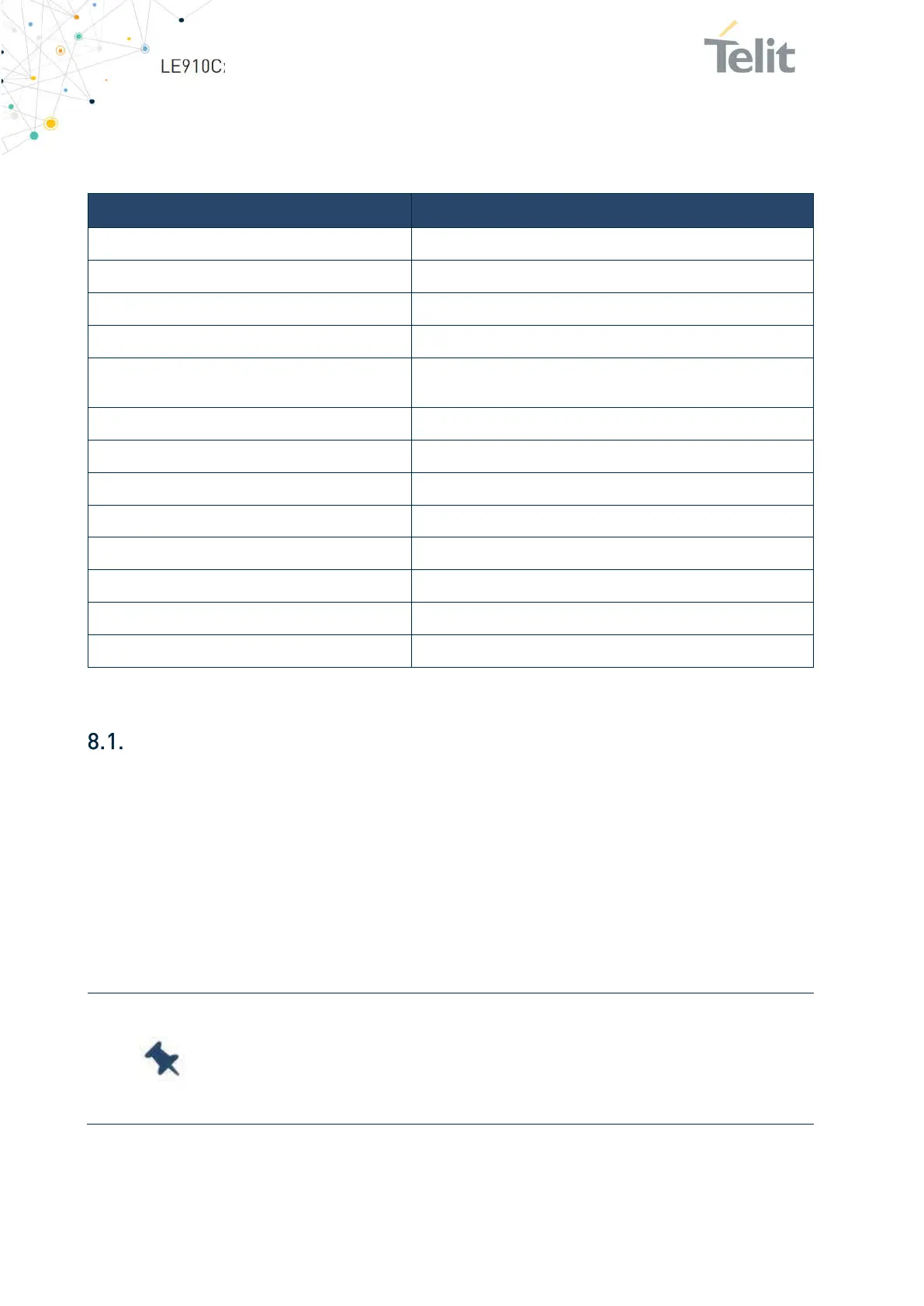
Table 25 summarizes all the hardware interfaces of the LE910Cx module.
Table 25: LE910Cx Hardware Interfaces
USB Port
The LE910Cx module includes a Universal Serial Bus (USB) transceiver, which operates
at USB high-speed (480Mbits/sec). It can also operate with USB full-speed hosts
(12Mbits/sec).
It is compliant with the USB 2.0 specification and can be used for control and data transfer
as well as for diagnostic monitoring and firmware update.
The USB port is typically the main interface between the LE910Cx module and OEM
hardware.
Interface LE910Cx
SGMII
For Ethernet support
HSIC
x1 (Optional)
SD/MMC
x1 dual voltage interface for supporting SD/MMC card
SDIO For WIFI support (1.8V only)
USB
USB2.0, OTG support on LE910C1-LA, LE910C4-LA and
LE910C4-CN
SPI
Master only, up to 50 MHz
I2C
For sensors, audio control
UART
2 HS-UART (up to 4 Mbps)
Audio I/F
I2S/PCM, Analog I/O
GPIO 10 ~ 27 (10 dedicated + 17 multiplexed with other signals)
USIM
x2, dual voltage each (1.8V/2.85V)
ADC
Up to x3
Antenna ports
2 for Cellular, 1 for GNSS
Note:
The USB_D+ and USB_D- signals have a clock rate of 480 MHz.
The signal traces must be routed carefully. Minimize trace lengths,
number of vias, and capacitive loading. The impedance value should
be as close as possible to 90 Ohms differential.
 Loading...


