LE910Cx Hardware Design Guide
1VV0301298 Rev.40 Page 73 of 149 2023-03-16
Not Subject to NDA
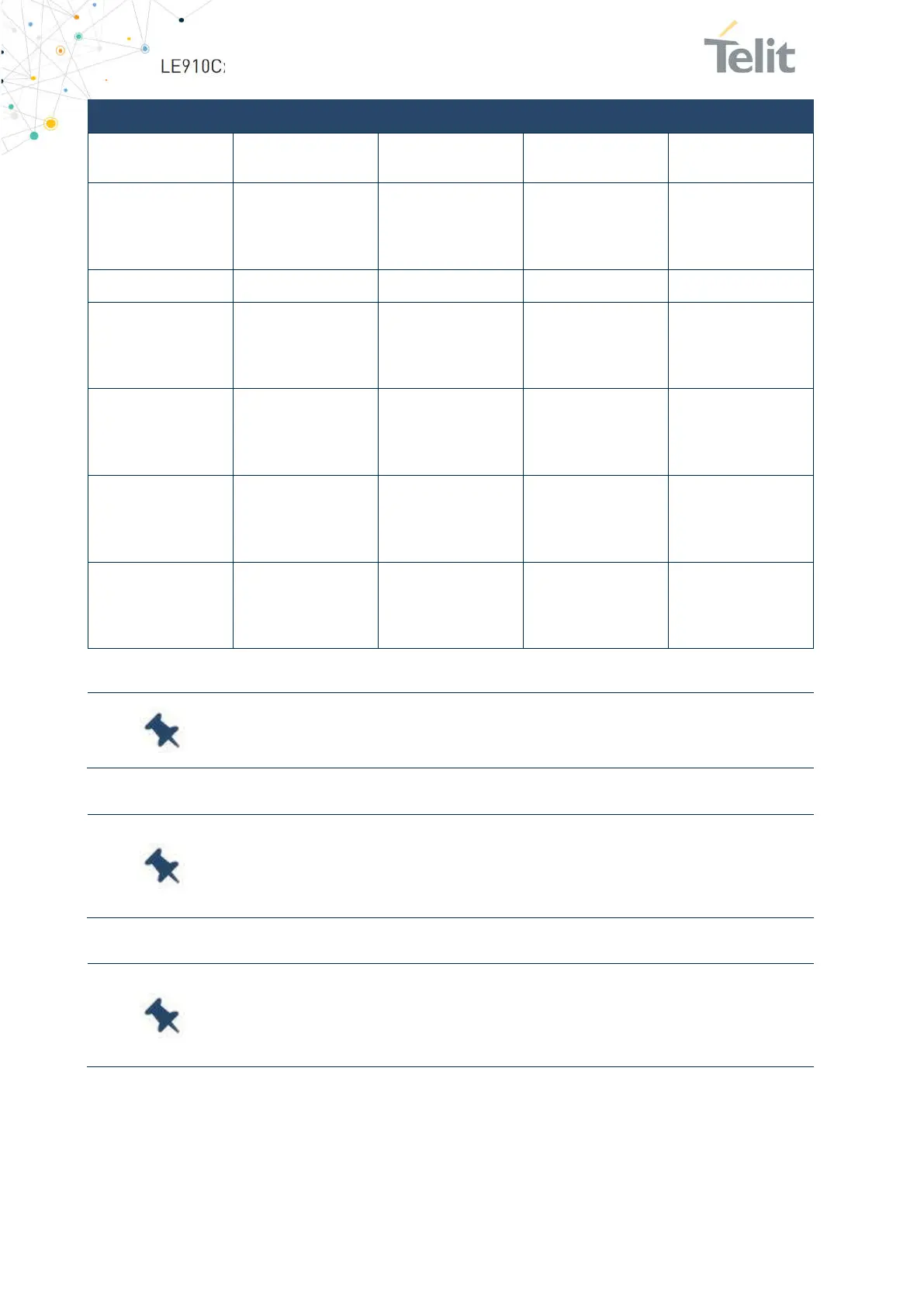
RS232 Pin# Signal Pad No. Name Usage
3 TXD -RX_UART N15
Receive line *see
Note
Input receive line of
LE910Cx UART
4 DTR - DTR_UART M14
Data Terminal
Ready
Input to LE910Cx
that controls the
DTE READY
condition
5 GND A2, B13, D4… Ground Ground
6 DSR - DSR_UART P14 Data Set Ready
Output from
LE910Cx that
indicates that the
module is ready
7 RTS - RTS_UART L14 Request to Send
Input to LE910Cx
controlling the
Hardware flow
control
8 CTS - CTS_UART P15 Clear to Send
Output from
LE910Cx controlling
the Hardware flow
control
9 RI - RI_UART R14 Ring Indicator
Output from
LE910Cx indicating
the Incoming call
condition
Table 28: Modem Serial Port 1 Signals
Note:
DCD, DTR, DSR, RI signals that are not used for UART
functions can be configured as GPIO using AT commands.
Note:
To avoid a back-powering effect, it is recommended to prevent
any HIGH logic level signal from being applied to the module’s digital
pins when it is powered OFF or during an ON/OFF transition.
Note:
For minimum implementations, only the TXD and RXD lines
need be connected. The other lines can be left open provided a
software flow control is implemented.
 Loading...


