30 MA365 • Rev. A2
Tellabs
®
6325 Edge Node 2 Installation Information
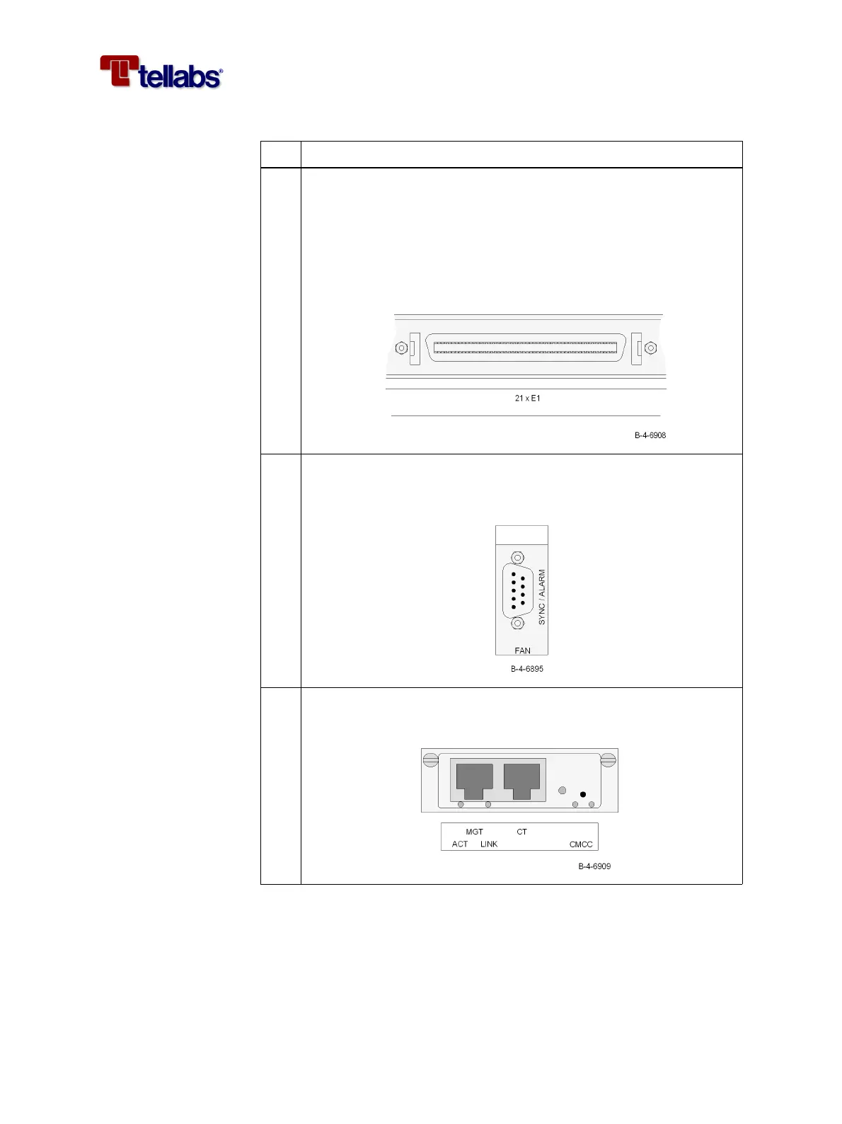
4 Connect the cable (120 ohm E1) for the 2 Mbit/s interfaces (E1) on the
PIM1 module. The coding of the open ended 120 ohm cable is shown
in ‘Pin designations on PIM1 connector and color coding of the E1
cable’ on page 64.
Note: If your configuration requires 75 ohm interfaces then external
baluns are required. See ‘To provide 75 ohm PIM1 interfaces’ on page
31.
5 Connect the cable for the synchronization and alarm interface
(SYNC/ALARM). The coding of the open ended 120 ohm cable is
shown in ‘Color coding of open ended cables’ on page 66.
6 Connect the Ethernet cable (MGT) for management of the Tellabs
6325 node.
Step Action