©2004 TESA Switzerland All Rights Reserved.
Page 2-12
User's Manual
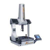
MH3D
Measuring System
The measuring system on the MH3D features glass scales which are etched
alternately of lines and spaces of equal width. The glass scales are firmly mounted
to each of the axes rails. These mountings allow the scale to expand and contract
along with the machine.
This system is represented schematically and consists of the following:
1. A light source
2. A reticle
3. A spacer
4. A line scale
5. A receiver
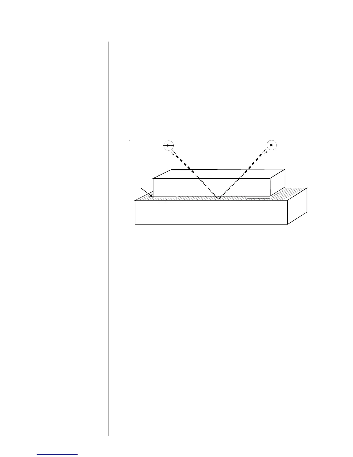
An opto-electrical procedure is used to read the incremental scale divisions.
According to the principle of reflected light, the scale division at the scanning
point is lit at an angle by a light source. The reflected light strikes a receiver
which converts the light energy to electrical energy.
The lines on the scale consist of a highly reflective material while the gaps are
non-reflective. A reticle, with divisions at the same intervals as the scale, is
moved directly over the scale.
The reticle, like the scale, is made of optical glass with opaque lines and transpar-
ent divisions. As the reticle is moved over the scale, the reflective lines of the
scale are alternately covered and uncovered. As the reticle lies between the scale
and the light source, the intensity of the light reaching the receiver varies as the
reticle or scale moves.
The light reaching the receiver generates periodic signals depending upon the
variations in light intensity. These signals are converted into digital measurement
signals which are used to measure the distance traveled along the scale.
The reticle has additional grating or sets of lines which is physically offset 1/4 of
a division (90 degrees) from the first grating. This grating has its own light source
and receiver. Its output signal is offset 90 degrees from the signal on the first
grating so one signal either precedes or follows the other signal depending on the
direction of travel. These signals are electronically evaluated to track the direction
of movement.
Reticle
Scale
Source
Receiver
Spacer