©2004 TESA Switzerland All Rights Reserved.
Page 3-10
User's Manual
MH3D
Moving the Axes
A position at the front of the machine is a comfortable one for most operations.
This permits easy access to the measuring envelope while watching the video
display on the MH3D enclosure.
The movement of each axis through the measuring envelope is accomplished by
pushing or pulling on the Z-rail. The Z-rail has finger pads at its lower end for
gripping. Stops are provided at both ends of the three axes to prevent overtravel.
Care should be taken to slow down when approaching the stops to prevent
banging.
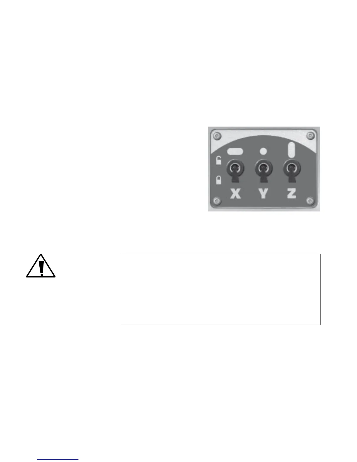
On the MH3D each axis is
provided with a locking system.
This system consists of three
switches, mounted on the left leg,
that control the flow of air to the
locking air bearings. Turning a
switch to "off" (down) deflates the
preloaded air bearings for that axis
and locks the axis.
The Z-rail counterbalance system
equalizes the weight of the rail so
that it moves easily up and down.
The regulator that controls the counterbalance is located at the right side of the
ZX carriage. It must be adjusted to compensate for varying probe weights. If the
counterbalance pressure is adjusted too low, it will trigger the safety valve
causing the Z-axis bearings to deflate and lock.
CAUTION
On the MH3D do not attempt to move any axis with the air supply
to that axis turned off.
Do not attempt to adjust the Z-rail counterbalance with the axis
locked. Hold the Z-rail firmly when unlocking the Z-axis. The rail,
if not properly adjusted, may move suddenly when the axis lock
is released.
On the MH3D, the axes can be precisely adjusted by means of a rod and bearing
arrangement that acts like a fine pitch screw. The rod is turned by means of
large, knurled knobs mounted on both ends of the X-axis and Y-axis and at the
lower end of the Z-axis. There are switches on each of the individual fine adjust
mechanisms that are used to engage or release the mechanism.