User's Manual
MH3D
©2004 TESA Switzerland All Rights Reserved.
Page 2-13
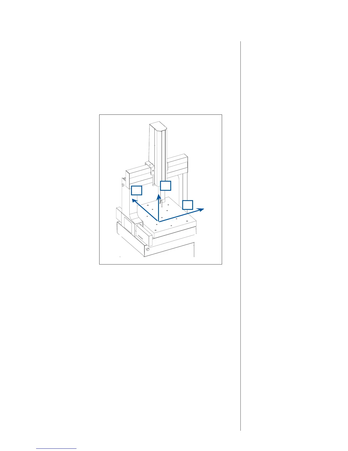
Reference Offsets
+Y!
+X!
+Z!
• All measurements are in millimeters.
• Values for the TESASTAR and TESASTAR_I are for the probe pointing
straight down. (A = 0°, B = 0°)
• Values were measured from the center of the hole in the bottom of the probe
holder in the MH3D. Values are in terms of machine coordinates.
• All values were measured with the probe detent engaged in the probe holder.
• All values should be verified by the machine operator.
Ball Probe:
X Axis: 0
Y Axis: 0
Z Axis: -70
TESASTAR
X Axis: -10
Y Axis: 0
Z Axis: -95
TESASTAR_I
X Axis: 0
Y Axis: -5.7
Z Axis: -76
The origin of the coordinate system shown represents the machine origin.
The arrows represent the positive direction of the machine's axes (in terms of
machine coordinates).
To verify the offsets, move the machine to the home position (upper, front, left
position) and read the machine position. This position (X,Y,Z) is the current
probe offsets.