DSP/BIOS Configuration Tool
3. Running the Linker
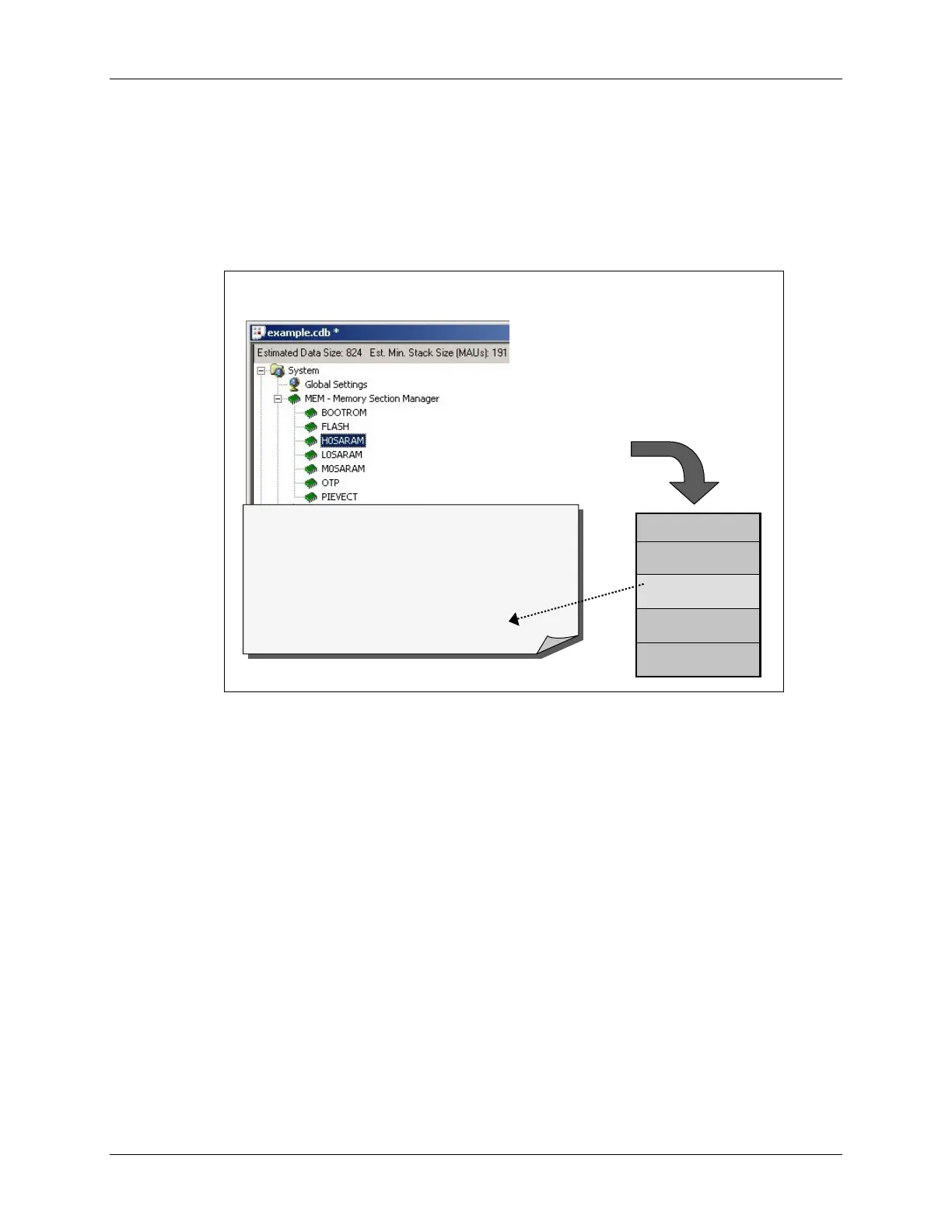
Creating the Linker Command File (via .CDB)
When you have finished creating memory regions and allocating sections into these memory
areas (i.e. when you save the .CDB file), the CCS configuration tool creates five files. One of the
files is BIOS’s cfg.cmd file — a linker command file.
Files Created by
Files Created by
Config
Config
Tool
Tool
Config
Config
tool generates five
tool generates five
different files
different files
Notice, one of them is the
Notice, one of them is the
linker command file
linker command file
CMD file is generated from
CMD file is generated from
your MEM settings
your MEM settings
*
*
cfg.h28
cfg.h28
*
*
cfg.h
cfg.h
*
*
cfg.cmd
cfg.cmd
*
*
cfg.s28
cfg.s28
*
*
cfg_c.c
cfg_c.c
MEMORY{
FLASH: org = 0x3D8000, len = 0x20000
H0SARAM: org = 0x3F8000, len = 0x2000
… }
SECTIONS{
.text: > FLASH
.bss: > M0SARAM
… }
MEMORY{
FLASH: org = 0x3D8000, len = 0x20000
H0SARAM: org = 0x3F8000, len = 0x2000
… }
SECTIONS{
.text: > FLASH
.bss: > M0SARAM
… }
This file contains two main parts, MEMORY and SECTIONS. (Though, if you open and
examine it, it’s not quite as nicely laid out as shown above.)
2 - 24 C28x - Programming Development Environment
 Loading...


