Sensor: 14 mm O.D.
15 turns, 0.15 mm trace
width
4 Layer
7.2 µH, 390 pF
12 MHz
SPI
USB
24-MHz
Xtal
1.8 V
SPI(SDO)
2.5 V
5 V
2.5 V
12 MHz
5 V
USB1.1+
Host
Computer
µUSB
LP5951
2.5 V Out LDO
LP5951
1.8 V Out LDO
MSP430F5528
x USB interface
x 12 MHz CLK to LDC1101
x SPI connection to LDC1101
MSP430 runs at 2.5 V for
24 MHz operation
Level
Shifter
SN74AVCH4T245
LDC1101
(WSON10)
CLKIN
SPI
Chapter 2
SNOU137–May 2015
EVM Features and Connections
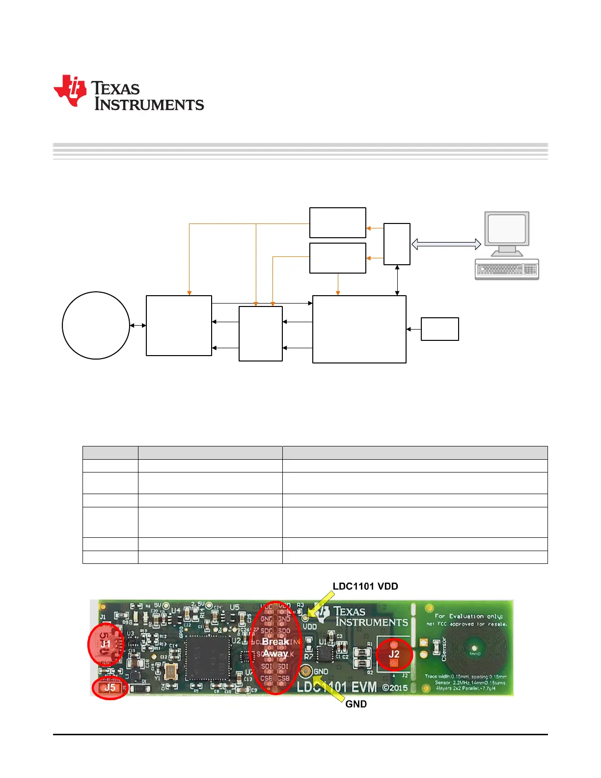
This section describes the connectors on the LDC1101EVM and how to properly connect, set up and use
the LDC1101. The EVM block diagram is shown below.
Figure 2-1. EVM Block Diagram
2.1 Connector Description
EVM Connections
Connector Type Functionality
J1 Micro-USB connector Provides power and control via PC USB connection
J2 Phoenix Connector 1727010 (not Provides convenient screw-terminal adapter for connecting various
installed) sensors
J5 100mil header (not installed) SPY-Bi-Wire connection for Code Composer Studio support.
Break-Away 7pin 100mil spaced pads The EVM can be separated at this point for remote placement of the
Header LDC1101 or to use a different MCU. Provides power and control interface
for the LDC1101.
VDD Via LDC1101 VDD supply voltage test point
GND Via Ground test point
Figure 2-2. Connector Locations
6
EVM Features and Connections SNOU137–May 2015
Submit Documentation Feedback
Copyright © 2015, Texas Instruments Incorporated