1.0
1.5
2.0
2.5
3.0
3.5
4.0
4.5
5.0
0.0 1.0 2.0 3.0 4.0 5.0 6.0 7.0 8.0 9.0 10.0
Rs ( )Ω
Frequency (MHz)
Break-Away Sections
www.ti.com
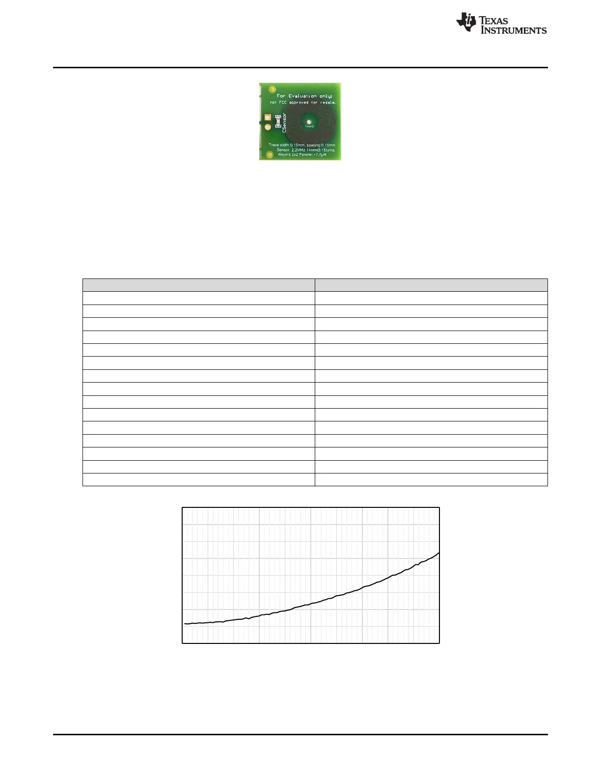
Figure 2-5. Default Inductive Sensor Section
The included sensor is a 4 layer circular coil with 2 parallel inductor paths. This is done to reduce the
parasitic series resistance (R
S
) of the sensor for improved parallel resonant impedance (R
P
) measurement
range. J3, a pair of 100mil separated thru-holes, is included for remote connection of the sensor.
A 1mm diameter un-plated thru-hole in the sensor center is available for mounting or alignment to an
external assembly.
LDC1101EVM Sensor Parameters
Parameter EVM Sensor Value
Outer Diameter 551 mils (14.0 mm)
Inner Diameter 191 mils (4.86 mm)
Number of turns 15
Trace Width 6 mils (0.152 mm)
Trace Spacing 6 mils (0.152 mm)
Number of layers 4
Trace Thickness 1 oz-cu (35 μm)
Inductance@ 3 MHz 7.2 µH
Sensor Capacitance 390 pF
f
SENSOR
(no target) 3.0 MHz
R
S
@ 3 MHz (no target) 1.8 Ω
R
P
@ 3 MHz (no target) 10.3 kΩ
Q@ 3 MHz 29
Approx. CPARASITIC 3 pF
SRF 33 MHz
Figure 2-6. LDC1101EVM Default Sensor Resistance Variation
8
EVM Features and Connections SNOU137–May 2015
Submit Documentation Feedback
Copyright © 2015, Texas Instruments Incorporated