www.ti.com
EVM Interface
2.2 EVM Interface
The LDC1101EVM is powered via the USB connection on J1. Use a micro-USB to USB-A cable to
connect the EVM to a PC. The LDC1101EVM draws its supply current from the USB port. Do not use a
passive USB hub with the EVM.
When powered on, the LDC1101EVM performs a quick self-test; if the LDC1101EVM is working properly
and the default EVM sensor is connected, the Green LED will illuminate. If the sensor is different, then the
Red LED will illuminate. When connected to the GUI, the Red LED is used to indicate data streaming.
LED Indicator Behavior with GUI
LED Color Functionality
D2 Green Indicates MCU is powered and the default sensor (or a similar sensor) is
connected.
D3 Red Indicates LDC1101 is in streaming mode, transferring conversion results to
host when illuminated.
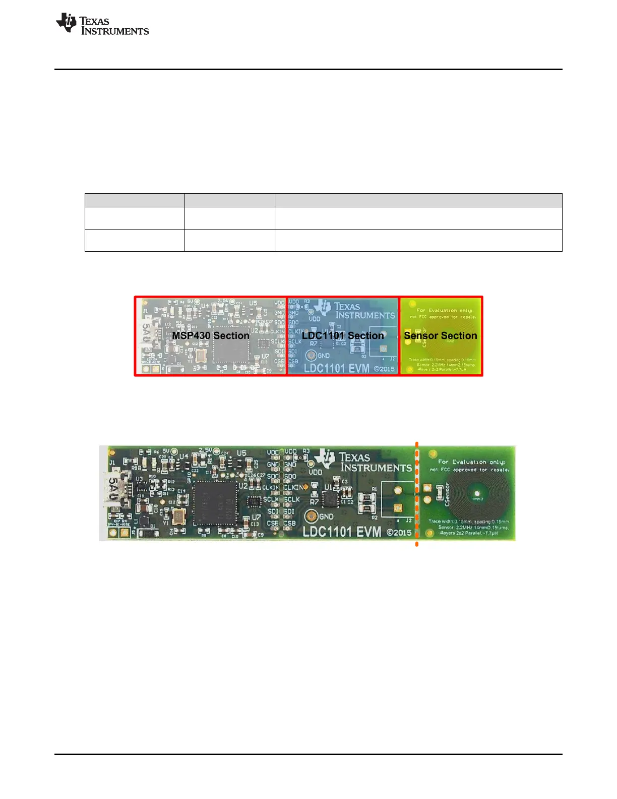
2.3 Break-Away Sections
Figure 2-3. EVM Break-Away Sections
The LDC1101 EVM can be broken into 3 discrete sections – a sensor section, which contains the sensor,
an LDC1101 section, and an MSP430 section which includes the USB interface section.
Figure 2-4. Break-Away Sensor
Break-Away Sensor Section
The sensor section of the LDC1101EVM can be broken along the indicated line to separate the sensor
from the LDC1101 IC. A two pin header is available for connecting the LDC1101 to alternative inductive
sensors. If the cable connection between the sensor and the LDC1101EVM is longer than 2cm, use
twisted pair or coaxial cable to connect the sensor to the LDC1101 section.
7
SNOU137–May 2015 EVM Features and Connections
Submit Documentation Feedback
Copyright © 2015, Texas Instruments Incorporated