www.ti.com
Break-Away Sections
LDC1101 Recommended Register Settings for EVM Sensor
Register Address Value
0x01 0x36
0x02 0xDD
0x03 0xFD
0x04 0xCX (set lower nibble based on desired response time)
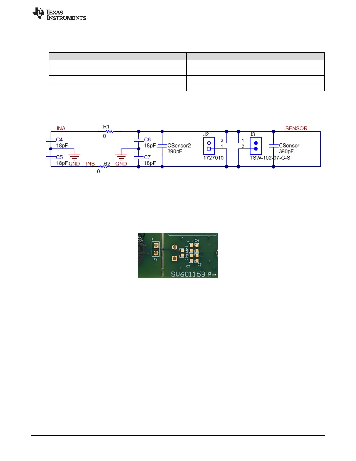
Sensor Configuration Options
Component footprints are available for a variety of configuration connections.
Figure 2-7. Sensor Configuration Options
When operating in an electrically noisy environment or with extended distances to a remote sensor, it may
be necessary to populate C4+C5 to improve the measurement ENOB. The components are left
unpopulated by default, and the footprints are located on the bottom of the PCB. For additional noise
suppression, R1 & R2 can be removed and a common-mode choke (e.g. SRF3216-222Y) can be placed
into those two footprints.
Figure 2-8. Unpopulated Footprints on EVM Bottom
In the rare case where EMI interference is caused by the LDC1101, it may be mitigated by populating
C6+C7 with capacitors that are approximately 10% of the value of C
SENSOR
. The components are left
unpopulated by default, and the footprints are located on the bottom of the PCB.
For some sensors, such as wire-wound inductors, it may not be easy to connect a sensor capacitor. A
second capacitor footprint – C
SENSOR2
- is included for such a situation. This is left unpopulated by default,
with the footprint located on the bottom of the PCB.
9
SNOU137–May 2015 EVM Features and Connections
Submit Documentation Feedback
Copyright © 2015, Texas Instruments Incorporated