Chapter 3: The TI-89 / TI-92 Plus Hardware Overview
13
TI
-
89 / TI
-
92 Plus Developer Guide
Not for Distribution
Beta Version January 26, 2001
The DBus protocol specifies a maximum bit time of two seconds. Link time-out
occurs if D0 or D1 remains low for longer than this time. Bit 13, when set,
disables the link time-out. If this bit is enabled, and D0 or D1 remain low for
longer than two seconds after the state machine has started to decode a byte, a
link interrupt is triggered and bit 7 is set to data error.
Bits 8–11 allow for enabling or disabling their corresponding interrupts. Bits 2–7
allow monitoring of the link port. These registers are modeled on RS232
control/status registers; programming serial IO on the TI
-
89 / TI
-
92 Plus is
somewhat akin to writing an RS232 handler.
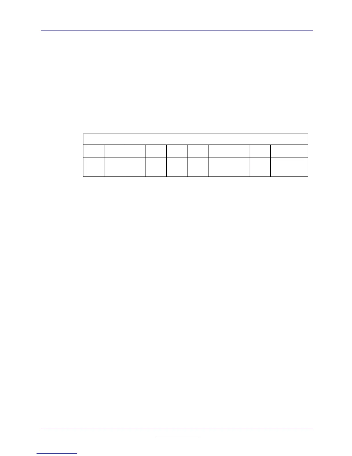
0x600014 Clock configuration — Clock / LCD control.
876543 2 1 0
One second
timer
LCD On
Table 3.7: Clock Configuration Register
Writing a 1 to Bit 2 of this register will trigger an autolevel 3 interrupt once per
second. Writing a 1 to Bit 0 of this register blanks the LCD.
 Loading...